| CF6-50 (GEK50481) ENGINE MANUAL | Revision No. 86 | Dated 01/15/2007 | |
| EM 72-22-01, REPAIR 008 | |||
| FAN FORWARD STATOR CASE - REPAIR - REWORK ABRADABLE SHROUD | |||
| CF6-50 ENGINE MANUAL | Dated: 01/15/2007 | |
| EM 72-22-01, REPAIR 008 | ||
| FAN FORWARD STATOR CASE - REPAIR - REWORK ABRADABLE SHROUD | ||
| * * * FOR ALL | ||
| TASK 72-22-01-300-008 |
| 1. | Rework Abradable Shroud. |
| A. | This repair gives instructions for a 360 degrees build-up of an existing abradable seal to achieve reduced fan blade clearance. Rework consists of removing the contaminated abradable material, bonding Nomex Core to the existing backsheet, and filling the Nomex Core with abradable material. Refer to Figure 901 thru Figure 905. |
| B. | The subsequent table gives a list of the part numbers that are applicable to this repair. All part numbers are applicable to all paragraphs unless specified differently. |
| 2. | Equipment and Material. |
| NOTE: | Equivalent substitutes may be used instead of the following items. |
| A. | Standard Equipment. None. |
| B. | Consumable Materials. |
| Code No. | Description |
|||
|---|---|---|---|---|
| C01-011 | Adhesive, Paste, Two Part (EA934NA adhesive) |
|||
| C04-005 | Solvent, General (solvent) |
|||
| C10-003 | Fabric, Glass (cloth) |
|||
| C10-008 | Honeycomb Core, Phenolic Reinforced Polyamid Fiber (Nomex core) |
|||
| C10-040 | Tape, Teflon |
|||
| C10-051 | Film, Release, Perforated (mylar) |
| C. | Special Tools. |
| Tool No. | Description |
|||
|---|---|---|---|---|
| 2C6902G01 | Fixture, Machine - Forward Fan Case |
|||
| 2C6916G01-3 | Fixture, Cutting - Shroud, Stage 1 Fan |
|||
| 2C7372G02 | Tool Set, Mach. - Stage 1 Fan Shroud |
|||
| 2C7448 | Fixture, Bonding - Fan Stator Honeycomb |
|||
| Locally Manufactured Screeding Template |
||||
| D. | Expendable Parts. None. |
| E. | SPAD Identification. |
| SPAD | Description |
|||
|---|---|---|---|---|
| 3041M98P02
| Nomex core |
|||
| 3041M98P03
| Nomex core |
|||
| 3042M21P01
| Backsheet |
|||
| 3049M50P01
| Backsheet |
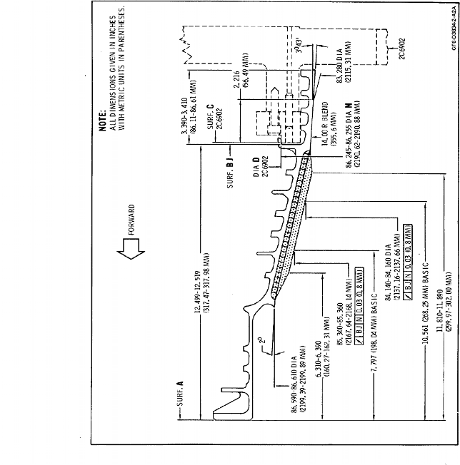
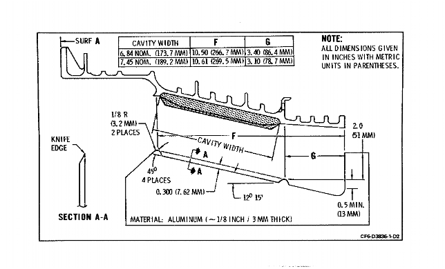
| 3. | Dimensional Information. |
| Refer to Figure 901. |
| 4. | Set-Up Information. |
| A. | Mount fixture 2C6902 on a vertical turret lathe with Surface C flat within 0.005 inch (0.13 mm) and the runout of Diameter D within 0.030 inch (0.76 mm) FIR. |
| B. | Install casing on fixture and clamp surface BJ flat using the ten fixture clamps. Torque clamp nuts to 70-110 lb-in. (7.9-12.4 N.m). |
| NOTE: | This information is provided for those rework sources desiring to remove abradable by machining and/or to do in-process machining. |
| 5. | Procedure. |
| NOTE: | This procedure may be accomplished with the acoustical liner segments installed provided they are protected from handling damage and are appropriately masked to prevent the entrance of abradable dust. |
| Subtask 72-22-01-390-001-051 |
| A. | Remove the six o'clock drain fitting as follows. |
| (1) | Remove the three 0.125 inch (3.18 mm) diameter rivets per 70-13-00 (TASK 70-13-00-390-001). |
| (2) | Shear the adhesive bond with a nylon bar positioned against the fitting flange. Retain fitting for re-assembly. |
| Subtask 72-22-01-160-001-054 |
| B. | Steam clean the casing per 70-21-03 (TASK 70-21-03-160-001). |
| Subtask 72-22-01-320-057 |
| C. | Remove abradable by machining. (Ref. Figure 902.) |
| (1) | Set up part on machining fixture. |
| NOTE: | For those operators not having fixture 2C6902 or a large VTL, the microballoon material may be removed with machining fixture 2C7372 while the case is still attached to the Fan/Core Assembly. |
| (2) | Remove the abradable by machining down to, but not into, the adhesive layer. When the tool contacts the adhesive layer, stop machining. Do not machine into the forward and aft edges of the cavity. |
| Subtask 72-22-01-350-073 |
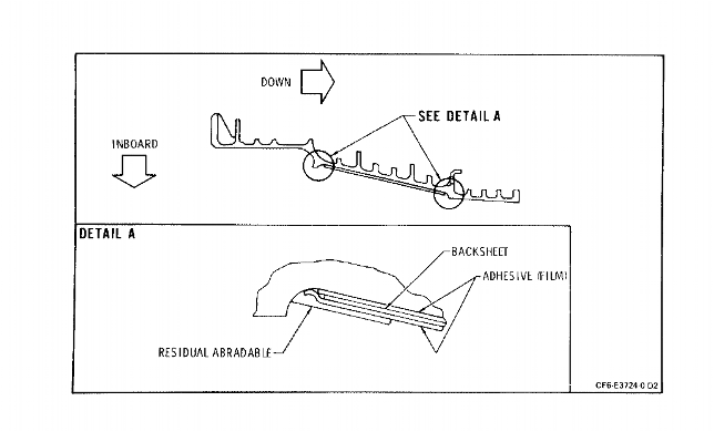
| D. | Remove abradable by sanding. (Ref. Figure 902.) |
| (1) | Place the casing in a suitable working position, such as on a wooden platform, skid, or in roll-over rings. |
| WARNING: | GRINDING DUST IS HARMFUL TO THE LUNGS. WEAR A RESPIRATOR AND POSITION A FAN OR EXHAUST VENT TO REMOVE DUST FROM THE WORK AREA. |
| (2) | Power sand using 80-240 grit aluminum oxide to remove the abradable down to, but not into, the adhesive layer. 100% of abradable is not required. A layer of abradable up to 0.060 inch (1.52 mm) thick is acceptable provided it is firmly attached and, visually, foreign materials are not present. Circumferentially, the final surface must be smoothly contoured without abrupt changes. Axially, the surface should be flat within 0.020 inch (0.51 mm) when checked with a straight edge. |
| Subtask 72-22-01-220-061 |
| E. | Inspect the shroud cavity. |
| (1) | Inspect for backsheet bond failure. None is allowed. If backsheets are loose, repair per (Subtask 72-22-01-360-079) paragraph 5.G. |
| (2) | Check surface for a smooth, gradually changing contour. Axially, the surface should be flat within 0.020 inch (0.51 mm) when checked with a straight edge. When a section of Nomex is lightly held against the cavity wall, gaps should not exceed 0.020 inch (0.51 mm). If required, remachine per (Subtask 72-22-01-350-073) paragraph 5.C. or sand per (Subtask 72-22-01-350-073) paragraph 5.D. |
| (3) | Inspect the shroud cavity for cleanliness. No foreign material such as soot, dirt, or oils, is allowed. If foreign material is present, steam clean per (Subtask 72-22-01-160-001-055) paragraph 5.F. If residual abradable indicates the presence of oil, remove the abradable by sanding with 180-240 grit aluminum oxide prior to steam cleaning. |
| Subtask 72-22-01-160-001-055 |
| F. | If inspection of the shroud cavity determines that steam cleaning is required, steam clean, with detergent, per 70-21-03 (TASK 70-21-03-160-001), with the following exceptions: |
| (1) | Direct the steam with a constant sweeping motion to prevent heat buildup. |
| (2) | Final steam pass must be without detergent. |
| (3) | After final rinse, vacuum dry with a wet/dry vacuum cleaner. |
| CAUTION: | PROTECT CAVITY AREA FROM CONTAMINATION. |
| (4) | Do not apply a rust preventive or any other foreign material. |
| Subtask 72-22-01-360-079 |
| G. | If inspection of the shroud cavity shows backsheet bond failure, repair as follows: |
| CAUTION: | USE CARE NOT TO REMOVE PARENT METAL FROM THE CASE. |
| (1) | Using a sharp knife or razor blade, cut the backsheet around the area to be repaired. Peel out the backsheet using a wood chisel or similar tool. Work from inside the delaminated area toward the cut. |
| (2) | Power sand using 220-240 grit aluminum oxide to remove residual adhesive and to scuff the casing. |
| (3) | Clean the repair area by vacuuming to remove dust and solvent C04-005 wipe. Immediately wipe dry with new, clean, absorbent paper towels. Allow surface to air dry normally. Do not touch or handle with bare hands. Wear clean white cotton gloves during completion of the repair. |
| (4) | Trim SPD backsheet (3042M21P01 or 3049M50P01) to fit the repair area. As an alternate to using a SPD backsheet, trim a piece of fiberglass cloth C10-003 approximately 1/8 inch (3.18 mm) smaller than the repair area. Impregnate with EA934NA adhesive C01-011 mixed in the ratio of 100 parts by weight of Part A (resin) to 33 parts by weight of Part B (catalyst). Pot life is approximately 40 minutes for a 133 gram batch. Squeegee the impregnated fiberglass to remove air bubbles and excessive adhesive. |
| (5) | Apply a thin uniform coat, approximately 0.010 inch (0.25 mm) thick, of adhesive C01-011 to the casing repair area and to mating face of SPD backsheet. Apply with a stiff bristle brush using a scrubbing action to wet out the surface completely. After wetting the surface, the adhesive may be leveled with a small squeegee. |
| (6) | Position the SPD backsheet or the impregnated fiberglass cloth smoothing out all wrinkles and insure that it is bonded without entrapping air. Place one ply of release film such as Teflon or Mylar C10-051 over the repair area followed by the application of a pressure vehicle which will impart 3-10 psi. |
| (7) | Cure for 4 hours minimum at 70-95° (21-35°C) |
| (7) A. | Optional Procedure. An optional cure method is to cure for one hour minimum at room temperature (60-100°F) (15.6-37.8°C) followed by a 175-200°F (79.4-93.3°C) cure for one hour minimum. A heat gun, heat lamps or heating blankets may be used. |
| (8) | Inspect for 100% bonding of the backsheet to casing. |
| Subtask 72-22-01-110-002-059 |
| H. | Prepare Nomex core kits as follows: |
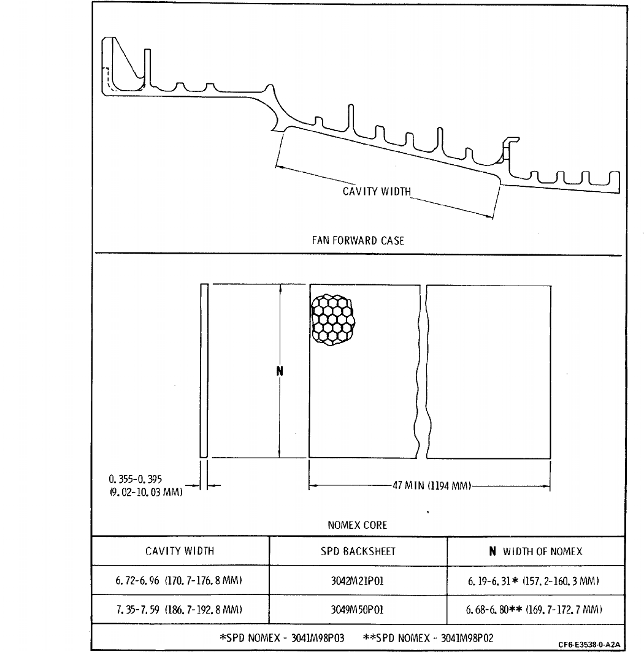
| (1) | Get either SPDs or Nomex core C10-008 of 0.375 inch (9.53 mm) cell size and nominal density of 3 pounds per cubic foot. External dimensions of the Nomex or the appropriate SPD will be determined by the cavity width. (Refer to Figure 903.) Six pieces per casing will be required. |
| (2) | Vapor degrease the core per 70-21-02 (TASK 70-21-02-110-002) for 10-15 seconds. Do not wipe, but let solvent drain and air dry. |
| (3) | Wearing clean white cotton gloves, place pieces in a clean plastic bag and seal until ready to install. |
| Subtask 72-22-01-360-080 |
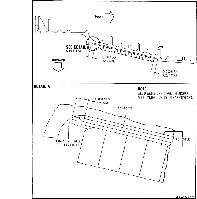
| I. | Lay up Nomex core as follows: (Refer to Figure 904.) |
| NOTE: | Due to the limited pot life of the EA934 adhesive (approximately 40 minutes), it is recommended that lay up and cure be performed in sections of approximately 1/3 the casing circumference. Since pot life and room temperature cure time will vary, it is suggested that a sample of approximately 0.015 inch (0.38 mm) thick be set aside and periodically checked to insure that curing has not begun before pressure is applied and that it has hardened before pressure is removed. Between Nomex sections, it will be necessary to remove excess cured adhesive to prevent interference. |
| (1) | Mix EA934NA adhesive C01-011 in the ratio of 100 parts by weight of Part A (resin) to 33 parts by weight of Part B (catalyst). |
| (2) | Apply a uniform coat, approximately 0.015 inch (0.38 mm) thick to the cavity backwall. Apply with a stiff bristle brush using a scrubbing action to wet out the surface completely. After wetting the surface, the adhesive may be leveled with a small squeegee. |
| (3) | Center the Nomex in the cavity and press into the adhesive film. Check to insure that there is no interference at the cavity edge fillets and that there is full contact between the Nomex and adhesive. If required the Nomex may be retained with Teflon tape C10-040. Install remaining Nomex sections same as first. Maximum gap between abutting ends is 0.120 inch (3.05 mm). Interlocking is not recommended since it will be more difficult to fill with abradable. Dry wipe to remove excessive adhesive. |
| Subtask 72-22-01-360-081 |
| J. | Pressurization and cure. |
| (1) | Place one ply of release film such as Teflon or Mylar C10-051 over the Nomex and apply uniform pressure of 3-10 psi (21-69 kPa) against the Nomex before the adhesive begins to cure. Maintain the pressure during cure. Pressure may be applied by vacuum bagging per Repair No. 7 (TASK 72-22-01-300-007), using pressure fixture 2C7448, or with pressure pads. During pressurization, protect the face and edges of the Nomex from damage. |
| (2) | Do a final cure at 70-95° (21-35°C) for 24 hours minimum. |
| (2) A. | Optional Procedure. Allow adhesive to cure a minimum of one hour at room temperature (60-100°F) (15.6-37.8°C). Immediate application of heat will cause the adhesive to sag. Final cure at 175-200°F (79.4-93.3°C) for two hours minimum. Heat may be applied with heat lamps, heating blankets or oven. |
| NOTE: | If lay up/curing is being performed in sections, the final cure may be delayed until the full 360° assembly has been completed. If this option is used, room temperature cure a minimum of 4 hours or until the adhesive has hardened before removing pressure. |
| Subtask 72-22-01-350-074 |
| K. | Visually check the Nomex cells for adhesive runs, bubbles, or blisters and for excessive adhesive outside the cavity. |
| (1) | Remove runs and/or break bubbles and blisters with an 1/8 inch (3.18 mm) diameter rotary file in an angled drill motor. |
| (2) | Blow off using clean, dry, filtered shop air. |
| Subtask 72-22-01-220-062 |
| L. | Visually inspect the Nomex bond. The bond must be visually sound with no unbonds allowed. |
| Subtask 72-22-01-930-061 |
| M. | Locally fabricate a screeding template (LMT0021) per Figure 905. |
| Subtask 72-22-01-360-001-082 |
| N. | Application of abradable seal material. |
| (1) | Mask off speed sensor holes by inserting a rolled piece of shim stock. Before rolling, apply Teflon tape to side which will be the OD. Insert to a depth which just clears the screeding template. |
| (2) | Tape mask both sides of the cavity. |
| (3) | Mix and apply abradable seal material per 70-43-15 (TASK 70-43-15-360-001) except as follows: |
| (a) | If part has been kept clean, solvent cleaning is not required. If Nomex was handled with bare hands or contaminated in any way, solvent C04-005 cleaning and thorough drying will be required. |
| CAUTION: | APPLY TOP COAT WHILE THE BOTTOM COAT IS STILL TACKY. |
| (b) | To minimize the exothermic reaction, the Nomex fill and build up must be performed in steps. The abradable must be forced into the cells so as to fill all the way to the bottom. It will be necessary to work the abradable back and forth and crosswise to accomplish the required fill. |
| (c) | Mix the following batch size: |
| MATERIAL | GRAMS |
|||||
|---|---|---|---|---|---|---|
| EPON 828 | 198-202 |
|||||
| Diethylenetriamine | 19.5-20.5 |
|||||
| Microballoons | 40-56 |
| (d) | Fill an initial 16-24 inch (406-610 mm) long section of Nomex. When the first 8-12 inch (203-305 mm) long section becomes tacky, trowel additional material on top and screed with the template. Fill a second 8-12 inch (203-305 mm) long section of Nomex. While this second section is becoming tacky, build up and screed the remaining 8-12 inches (203-305 mm) of the initial section. Continue this two-step build-up until part is completed. |
| (e) | A skim coat of abradable seal material may be optionally applied after screeding. |
| (f) | Remove masking tape and speed sensor plugs and cure per 70-43-15 (TASK 70-43-15-360-001). |
| Subtask 72-22-01-360-001-082 |
| N. A. | Application of abradable seal material. |
| (1) | Mask off speed sensor holes by inserting a rolled piece of shim stock. Before rolling, apply Teflon tape to side which will be the OD. Insert to a depth which just clears the screeding template. |
| (2) | Tape mask both sides of the cavity. |
| (3) | Mix and apply abradable seal material per 70-43-15 (TASK 70-43-15-360-001) except as follows: |
| (a) | If part has been kept clean, solvent cleaning is not required. If Nomex was handled with bare hands or contaminated in any way, solvent C04-005 cleaning and thorough drying will be required. |
| CAUTION: | APPLY TOP COAT WHILE THE BOTTOM COAT IS STILL TACKY. |
| (b) | To minimize the exothermic reaction, the Nomex fill and build up must be performed in steps. The abradable must be forced into the cells so as to fill all the way to the bottom. It will be necessary to work the abradable back and forth and crosswise to accomplish the required fill. |
| (c) | Mix the following batch size: |
| MATERIAL | GRAMS |
|||||
|---|---|---|---|---|---|---|
| EPON 828 | 441-459 |
|||||
| Diethylenetriamine | 42.8-47.3 |
|||||
| Microballoons | 90-126 |
| (d) | Divide Nomex area into eight segments by applying polyester or Teflon tape C10-040. Fill Nomex in, one segment at a time, using material from one mix. Discard excess from each batch. Prepare fresh batches for each of the eight segments. After filling all segments, apply a top coat, starting at first segment filled, and screed with the template. The top coat may be allowed to gel before application. |
| (e) | A skim coat of abradable seal material may be optionally applied after screeding. |
| (f) | Remove masking tape and speed sensor plugs and cure. Refer to TASK 70-43-15-360-001 (70-43-15, Abradable Plastic Seal Compound). |
| Subtask 72-22-01-320-056 |
| O. | Machine abradable as follows: |
| NOTE: | Figure 901 indicates in-process dimensions. Final machining is performed during assembly to meet rotor blade clearance. As an alternative, in-process machining may be deleted and all machining performed during TASK 72-20-01-430-000 (72-20-01, Assembly), using fixtures 2C7372 or 2C6916. The gap between screeding template and abradable should not exceed 0.075 inches (1.91 mm) to insure clean up. |
| (1) | Set up part on machine. |
| (2) | Machine to requirements of Figure 901. |
| Subtask 72-22-01-350-075 |
| P. | Remove overhanging abradable at the speed sensor boss by either blending flush to 0.040 inch (1.02 mm) larger than the boss hole or by using a 1.50 inch (38.1 mm) diameter sheet metal hole saw. |
| Subtask 72-22-01-360-001-084 |
| Q. | Visually inspect abradable material for surface voids. Repair voids larger than 0.050 inch (1.27 mm) per 70-43-15 (TASK 70-43-15-360-001). |
| Subtask 72-22-01-360-001-088 |
| R. | Audibly check adhesion of abradable seal to casing by tapping seal with a steel rod approximately 3/8 inch (9.5 mm) diameter, 2 inches (51 mm) long with a rounded end. Use sufficient force to obtain the degree of sound required. Loose areas will have a "clicking" sound compared to a "solid" sound for properly bonded areas. If defective, remove and replace per 70-43-15 (TASK 70-43-15-360-001). |
| Subtask 72-22-01-390-002-052 |
| S. | Replace six o'clock drain fitting as follows: |
| (1) | Clean off old adhesive by power sanding with 220-240 grit aluminum oxide and solvent C04-005 wipe. |
| (2) | Apply a thin uniform coat of EA934 C01-011 , mixed per manufacturers recommendations. |
| (3) | With the flat on the connector aft, align rivet holes. Install three rivets, MS20427M4-7, per 70-13-01 (TASK 70-13-01-390-002). |
| (4) | Wipe off excessive adhesive on both ID and OD of the drain fitting. |