| CF6-50 (GEK50481) ENGINE MANUAL | Revision No. 86 | Dated 07/15/2008 | |
| EM 78-32-00 | |||
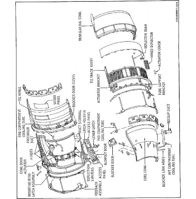
| FAN REVERSER RIGHT OR LEFT HALF - ASSEMBLY | |||
| CF6-50 ENGINE MANUAL | Dated: 07/15/2008 | |
| EM 78-32-00 | ||
| FAN REVERSER RIGHT OR LEFT HALF - ASSEMBLY | ||
| * * * FOR 50C, 50C1, 50C2, 50C2-B, 50C2-F, 50C2-R, 45A2, 50E, 50E1, 50E2 | ||
| TASK 78-32-00-440-000 |
| 1. | Tools, Equipment, and Material. |
| (Refer to Figure 1001 thru Figure 1019.) |
| NOTE: | Equivalent alternatives are permitted for tools, equipment, and consumable materials. |
| A. | Standard Equipment. None. |
| B. | Consumable Materials. |
| Code No. | Description | Manufacturer | Use |
|
|---|---|---|---|---|
| C01-089 | Pro Seal 735 (aluminum) | Essex Chemical Corp. 1401 Broad St. Clifton, NJ 07015 | Seal sound panels |
|
| C02-003 | Molykote 321-R FSCM 94499 | Dow Corning Corp. 45 Commerce Dr. Trumball, CN 06601 | Lubricate feed back cams |
|
| C02-014 | Grease, Molybdenum, Disulphite MIL-G-21164, Aero Shell 17 | Shell Oil Co. One Shell Plaza Houston, TX 77002 USA | Lubricate the ballscrew actuator |
| C. | Special Tools. |
| Tool No. | Description |
|||
|---|---|---|---|---|
| 2C6111G01 | Stand, Assembly/Disassembly and Test Fan Reverser |
|||
| 2C6366G01 | Sling, Fan Reverser Lift |
|||
| 2C6367G01 | Puller, Actuator Pin |
|||
| 2C6368G01 | Sling and Bracket Assy., Translating Cowl Lift |
|||
| 2C6512G01 | Jack Set, Translating Cowl |
| D. | Expendable Parts. None. |
| E. | SPD Identification. None. |
| 2. | General. |
| A. | The following procedure provides instructions for the assembly of the fan reverser. |
| * * * FOR 50C, 50C1, 50C2, 50C2-B, 50C2-F |
| NOTE: | The configuration of a fan reverser is determined by the position the reverser is to be installed on the aircraft. The following differences should be observed: (a) the assembly pattern of vaned deflectors, (b) the deflection limiter immediately forward of cowl door actuator is installed on tail engine reversers only; the limiter immediately aft of the cowl door actuator is installed only on wing engine reversers, and (c) the tail adapter is installed only on reversers to be installed on tail engines. |
| * * * FOR 45A2, 50C, 50C1, 50C2, 50C2-R, 50E, 50E1, 50E2 |
| NOTE: | The configuration of a fan reverser is determined by the position the reverser is to be installed on the aircraft. The difference is observed in the assembly pattern of the vaned deflectors. |
| * * * FOR 45A2, 50C, 50C1, 50C2, 50C2-B, 50C2-F, 50C2-R, 50E, 50E1, 50E2 |
| 3. | Assembly. |
| Assemble the fan reverser as follows: (Refer to Figure 1001). |
| Subtask 78-32-00-440-051 |
| CAUTION: | WHEN ASSEMBLING COMPONENTS, MAKE CERTAIN THAT THE CORRECT CONFIGURATION IS USED; REFER TO THE APPLICABLE ILLUSTRATED PARTS CATALOG (IPC) AND FIGURES. |
| A. | Install support assembly in stand, 2C6111, with sling, 2C6366, and hoist. Position assembly in vertical position with leading edge flange down. |
| Subtask 78-32-00-440-052 |
| B. | Install the wear pads at latch brackets on support assembly. Tighten bolts and nuts to 24-27 lb. in. (2.7-3.1 N.m). |
| Subtask 78-32-00-440-053 |
| C. | Install lower latches to support, install bolts, bushings and nuts. Tighten aft latch bolts to 190-220 lb-in. (21.5- 24.8 N.m); tighten mid and forward latch bolts to 480-570 lb-in. (54.2-64.4 N.m). Spray latch hook contact areas with lubricant C02-003 |
| Subtask 78-32-00-440-054 |
| D. | Install deflection limiters; tighten bolts to 24-27 lb.in. (2.7-3.1 N.m). |
| * * * FOR 45A2, 50C, 50C1, 50C2, 50C2-R, 50E, 50E1, 50E2 |
 |
| Figure 1001 (Sheet 2) Fan Reverser Assembly |
| Subtask 78-32-00-440-055 |
| * * * FOR 45A2, 50C, 50C1, 50C2, 50C2-B, 50C2-F, 50C2-R, 50E, 50E1, 50E2 |
| E. | Install cooling manifold to support, tighten screws 24-27 lb. in. (2.7-3.1 N.m); install clamps. |
| Subtask 78-32-00-440-056 |
| F. | Install precooler duct and brackets to support, right side only); tighten bolts to 24-27 lb-in. (2.7-3.1 N.m). |
| Subtask 78-32-00-440-057 |
| G. | Install link box assemblies to support, tighten screws to 24-27 lb-in. (2.7-3.1 N.m). |
| Subtask 78-32-00-440-058 |
| H. | Install Sound panels to support, tighten screws to 24-27 lb-in. (2.7-3.1 N.m). Shim if required/necessary. |
| Subtask 78-32-00-440-059 |
| I. | Install the deflector aft support ring to the support assembly. Tighten bolts and nuts to 24-27 lb.in. (2.7-3.1 N.m). |
| Subtask 78-32-00-440-060 |
| J. | Install deflector beams to aft support ring. Tighten bolts to 24-27 lb.in. (2.7-3.1 N.m). |
| NOTE: | The screws that secure the wear strip to the beam must be a minimum of 0.040 in. (1.0 mm) below the wear strip surface and a minimum of 0.010 inch (0.3 mm) below the metal of the beam surface. |
| NOTE: | A "Neutral" reverser half may be assembled by installing (4) blank deflectors at positions 4, 7, 10 and 13, for shipping/storage, because of unknown engine position. Tag the reverser with the following or equivalent, attached to the center actuator drive shaft input connector. |
| Subtask 78-32-00-440-061 |
| CAUTION: | THIS ASSEMBLY IS INCOMPLETE AND MUST HAVE THE APPROPRIATE ENGINE POSITION CASCADE CONFIGURATION INSTALLED, PRIOR TO FLIGHT. |
| * * * FOR 50C, 50C1, 50C2, 50C2-R |
| K. | The deflectors are installed as follows for the A300 aircraft. Refer to Figure 1002 and Figure 1003. |
| (1) | Left Side (position No. 1) Right Side (position No. 2). |
| (a) | At positions 1 through 4, 7 and 9 through 13 use straight vaned deflectors. |
| (b) | At positions 5, 14 and 15 use 45 degree angle vaned deflectors with angle pointing "UP". |
| (c) | At positions 6 and 16 use blocked deflectors. |
| (d) | At position 8 use 45 degree angle vaned deflector with angle pointing "DOWN". |
| (e) | Tighten bolts 24-27 lb-in. (2.7-3.1 N.m) and countersunk screws on inner deflector 13-16 lb-in. (1.5-1.8 N.m). |
| (2) | Right Side (position No. 1) Left Side (position No. 2). |
| (a) | At positions 1 through 4, 14 and 15 use 45 degree vaned deflectors with angle pointing "UP". |
| (b) | At positions 6 and 9 through 13 use straight vaned deflectors. |
| (c) | At positions 7 and 8 use 45 degree angle vaned deflectors with angle pointing "DOWN". |
| (d) | At positions 5 and 16 use blocked deflectors. |
| (e) | Tighten bolts 24-27 lb-in. (2.7-3.1 N.m) and countersunk screws on inner deflectors 13-16 lb-in. (1.5-1.8 N.m). |
| Subtask 78-32-00-440-078 |
| * * * FOR 50C, 50C1, 50C2, 50C2-B, 50C2-F |
| L. | The deflectors are assembled to the support assembly as follows for the DC10-30 Aircraft. Refer to Figure 1004, Figure 1005 and Figure 1006. |
| (1) | Right side (Pos. 1) Left side (Pos. 3) (aft looking forward). |
| (a) | At positions 1 through 4, 15 and 16, install 45 degree angle vaned deflectors with angle pointing "UP". |
| (b) | At positions 7 and 8, install 45 degree angle vaned deflectors with angle pointing "DOWN". |
| (c) | At positions 9 through 14, install straight vaned deflectors. |
| (d) | At positions 5 and 6, install blocked deflectors. |
| (e) | Tighten bolts 24-27 lb-in. (2.7-3.1 N.m) and countersunk screws on inner deflectors 13-16 lb-in. (1.5-1.8 N.m). |
| (2) | Left side (Pos. 1) Right side (Pos. 3) (aft looking forward). |
| (a) | At positions 1 through 4 and 9 through 14, install straight vaned deflectors. |
| (b) | At positions 5, 15 and 16, install 45 degree angle vaned deflectors with angle pointing "UP". |
| (c) | At position 8 install a 45 degree angle vaned deflector with angle pointing "DOWN". |
| (d) | At positions 6 and 7, install blocked deflectors. |
| (e) | Tighten bolts 24-27 lb-in. (2.7-3.1 N.m) and countersunk screws on inner deflectors 13-16 lb-in. (1.5-1.8 N.m). |
| (3) | Left and Right side of Pos. No. 2 (aft looking forward). |
| (a) | At positions 1, 2, 3, 12 and 13, install 45 degree angled vaned deflectors with angle pointing "DOWN". |
| (b) | At positions 4, 5 and 6 install straight vaned deflectors. |
| (c) | At positions 7, 8 and 9, install 45 degree angled vaned deflectors with angle pointing "UP". |
| (d) | At positions 10 and 11 install blocked deflectors. |
| (e) | At positions 14, 15 and 16, install 105 degree angled vaned deflectors with angle pointing "UP". |
| (f) | Tighten bolts 24-27 lb-in. (2.7-3.1 N.m) and countersunk screws on inner deflectors 13-16 lb-in. (1.5-1.8 N.m). |
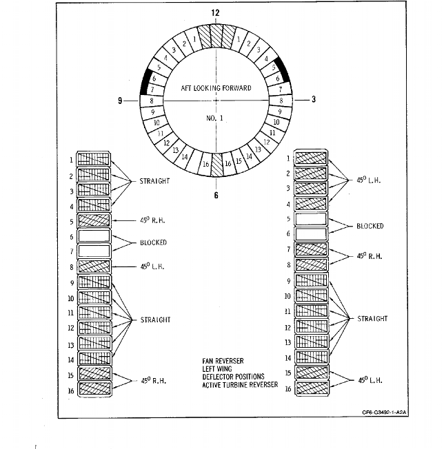
| NOTE: | Figure 1007 and Figure 1008 show the deflector positions for engines equipped with fixed core exhaust nozzles and deactivated turbine reversers. Refer to SB 78-0161. |
| * * * FOR 45A2, 50C, 50C1, 50C2, 50C2-B, 50C2-F, 50C2-R, 50E, 50E1, 50E2 |
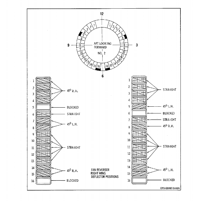 |
| Figure 1002 Fan Reverser Right Wing Deflector Positions for A300 Aircraft |
| * * * FOR 45A2, 50C, 50C1, 50C2, 50C2-B, 50C2-F, 50C2-R, 50E, 50E1, 50E2 |
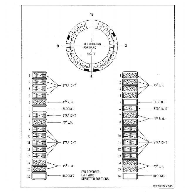 |
| Figure 1003 Fan Reverser Left Wing Deflector Positions for A300 Aircraft |
| * * * FOR 45A2, 50C, 50C1, 50C2, 50C2-B, 50C2-F, 50C2-R, 50E, 50E1, 50E2 |
 |
| Figure 1004 Fan Reverser Left Wing Deflector Pattern for DC10 or KC10 Aircraft |
| * * * FOR 45A2, 50C, 50C1, 50C2, 50C2-B, 50C2-F, 50C2-R, 50E, 50E1, 50E2 |
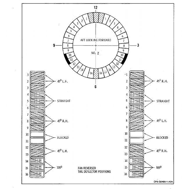 |
| Figure 1005 Fan Reverser Tail Engine Deflector Pattern for DC10-30 Aircraft |
| * * * FOR 45A2, 50C, 50C1, 50C2, 50C2-B, 50C2-F, 50C2-R, 50E, 50E1, 50E2 |
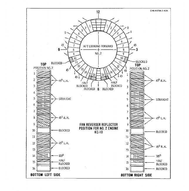 |
| Figure 1005A. Fan Reverser Tail Engine Deflector Pattern for KC10 |
| * * * FOR 45A2, 50C, 50C1, 50C2, 50C2-B, 50C2-F, 50C2-R, 50E, 50E1, 50E2 |
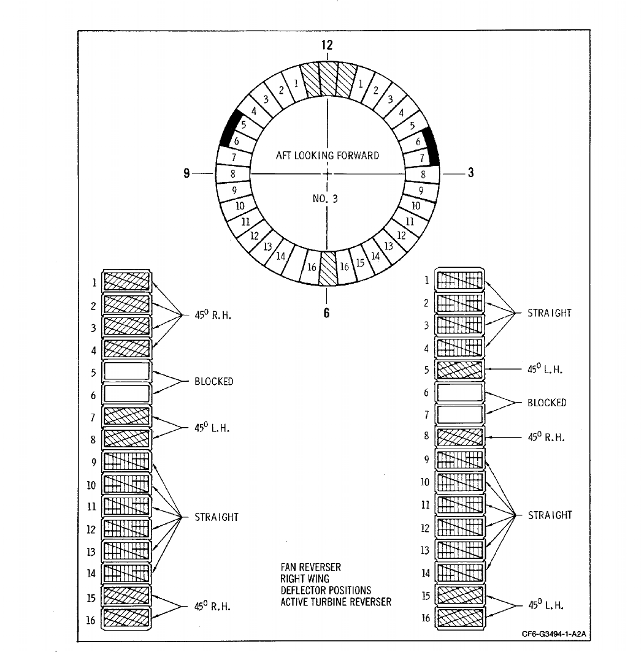 |
| Figure 1006 Fan Reverser Right Wing Deflector Pattern for DC10-30 or KC10 Aircraft |
| * * * FOR 45A2, 50C, 50C1, 50C2, 50C2-B, 50C2-F, 50C2-R, 50E, 50E1, 50E2 |
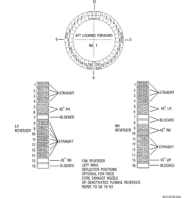 |
| Figure 1007 Fan Reverser Left Wing Deflector Pattern for DC10-30 or KC10 Aircraft with Fixed Cowl Exhaust Nozzles (Position 1) |
| Subtask 78-32-00-440-079 |
| * * * FOR 45A2, 50E, 50E1, 50E2 |
| M. | The deflectors are installed to the support assembly as follows for the "747" aircraft. Refer to Figure 1009. |
| (1) | Left and Right side deflector pattern - (aft looking forward). |
| (a) | At positions 1 through 5, 11, 12 and 13, install straight vaned deflectors. |
| (b) | At positions 6 through 9, 14 and 15, install 45 degree angled deflectors with angle pointing "UP". |
| (c) | At positions 10 and 16, install blocked deflectors. |
| (d) | Tighten bolts 24-27 lb-in. (2.7-3.1 N.m) and countersunk screws on inner deflectos 13-16 lb-in. (1.5-1.8 N.m). |
| * * * FOR 45A2, 50C, 50C1, 50C2, 50C2-B, 50C2-F, 50C2-R, 50E, 50E1, 50E2 |
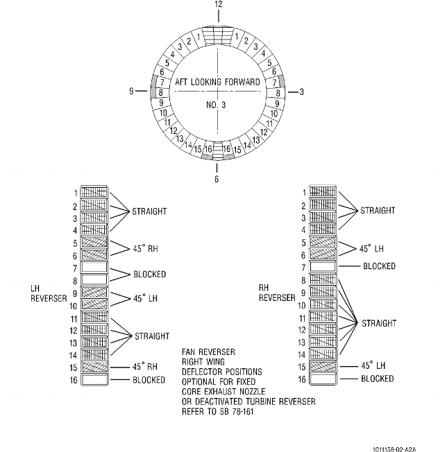 |
| Figure 1008 Fan Reverser Right Wing Deflector Pattern for DC10 or KC10 with Fixed Core Exhaust Nozzle. (Position 3) |
| * * * FOR 45A2, 50C, 50C1, 50C2, 50C2-B, 50C2-F, 50C2-R, 50E, 50E1, 50E2 |
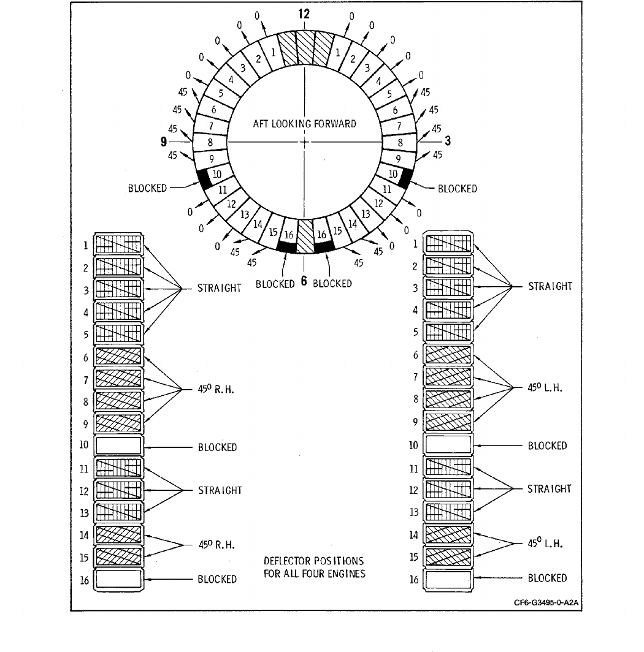 |
| Figure 1009 Fan Reverser Deflector Pattern for "747" |
| Subtask 78-32-00-440-062 |
| * * * PRE SB 78-3013 ( FAN REVERSERS WITHOUT AN ELECTROMECHANICAL THRUST REVERSER ACTUATION SYSTEM (TRAS) LOCK FOR BOEING 747 ) |
| * * * PRE SB 78-3025 ( FAN REVERSERS WITHOUT AN ELECTROMECHANICAL THRUST REVERSER ACTUATION SYSTEM (TRAS) LOCK FOR BOEING DC-10 ) |
| N. | Install the actuator brackets to the support assembly. Tighten the bolts to 55-70 lb in. (6.2-7.9 N.m). Install seals and seal retainers on the brackets. Tighten the bolts and nuts to 24-27 lb in. (2.7-3.1 N.m). |
| (1) | Install the nipples, washers and jam nuts at the upper bracket. Tighten jam nuts to 180-200 lb in. (20.3-22.6 N.m) and safetywire. |
| (2) | Install the connecting link at the forward mount clevis. Install the bolt (pointing aft) and washers. Tighten nut up to 50 lb in. (5.6 N.m) and insert a cotter pin. |
| * * * END PRE SB 78-3013 |
| * * * END PRE SB 78-3025 |
| Subtask 78-32-00-440-080 |
| * * * SB 78-3013 ( FAN REVERSERS WITH AN ELECTROMECHANICAL THRUST REVERSER ACTUATION SYSTEM (TRAS) LOCK FOR BOEING 747 ) |
| * * * SB 78-3025 ( FAN REVERSERS WITH AN ELECTROMECHANICAL THRUST REVERSER ACTUATION SYSTEM (TRAS) LOCK FOR BOEING DC-10 ) |
| N. A. | Install the actuator bracket and the mount tower support brackets as follows: |
| (1) | Install the actuator brackets at the upper and lower actuator locations. Tighten the bolts to 55-70 lb in. (6.2-7.9 N.m). Install seals and seal retainers on the brackets. Tighten the bolts and nuts to 24-27 lb in. (2.7-3.1 N.m) |
| (2) | Fit the actuator bracket to the center actuator location. Install the radius spacers on the mating mount tower flange surfaces and install shims as necessary to prevent any gaps between the actuator housing flange and the radius spacers. Attach the actuator bracket and the radius spacers to the aft torque box ring with four self-locking nuts, four washers, and four self-locking bolts. Tighten the bolts to 55-70 lb in. (6.2-7.9 N.m). Install seals and seal retainers on the brackets. Tighten the bolts and nuts to 24-27 lb in. (2.7-3.1 N.m). |
| (3) | Install the mount tower supports at the center actuator location with 22 blind rivets or 22 bolts/collars. Tighten the bolts to 33-37 lb in. (3.7-4.2 N.m). |
| (4) | Install the nipples, washers and jam nuts at the upper bracket. Tighten jam nuts to 180-200 lb in. (20.3-22.6 N.m) and safetywire. |
| (5) | Install the connecting link at the forward mount clevis. Install the bolt (pointing aft) and washers. Tighten nut up to 50 lb in. (5.6 N.m) and insert a cotter pin. |
| * * * END SB 78-3013 |
| * * * END SB 78-3025 |
| Subtask 78-32-00-440-063 |
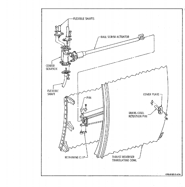
| O. | Install cowl door ball screw actuator and flexible shaft. (Refer to Figure 1010 and Figure 1012). |
| NOTE: | If hydraulic actuator system is installed, follow paragraph 3.N. (Subtask 78-32-00-440-064) and reference Figure 1011, Figure 1013 and Figure 1014 for hard line routing. |
| (1) | Position actuator on cowl bracket with input connector forward. Install bolts and nuts; tighten to 55-70 lb in. (6.2-7.9 N.m). |
| (2) | Install flexible shaft through deflector bracket and insert in actuator input; tighten coupling nut, finger tight, then back off one-half turn. |
| (3) | Rotate shaft core two revolutions to center shaft washer on actuator connection; tighten coupling nut to 25-45 lb in. (2.8-5.1 N.m) and safetywire. |
| (4) | Secure shaft input housing to support; tighten bolts to 55-70 lb-in. (6.2-7.9 N.m). |
| (5) | Route shaft along inner cowl forward of link box assemblies and clamp; tighten clamp bolts to 24-27 lb in. (2.7-3.1 N.m). |
| NOTE: | Install clamps fingertight. Pull shaft snug beginning at actuator, then tighten successive clamps from top to bottom. Ensure that shaft slack is distributed between second and third clamps from bottom. |
| NOTE: | Clamp center line must be aligned with shaft center line. Bend radii must be 6.5 inches (165.1 mm) or more. |
| * * * FOR 45A2, 50C, 50C1, 50C2, 50C2-B, 50C2-F, 50C2-R, 50E, 50E1, 50E2 |
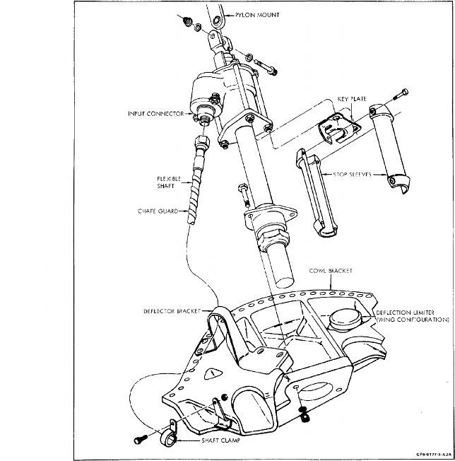 |
| Figure 1010 SB 78-133 Cowl Door Actuator Installation |
| * * * FOR 45A2, 50C, 50C1, 50C2, 50C2-B, 50C2-F, 50C2-R, 50E, 50E1, 50E2 |
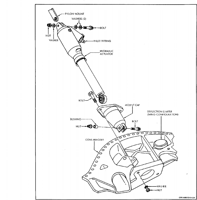 |
| Figure 1011 Cowl Door Hydraulic Actuator Installation |
| * * * FOR 45A2, 50C, 50C1, 50C2, 50C2-B, 50C2-F, 50C2-R, 50E, 50E1, 50E2 |
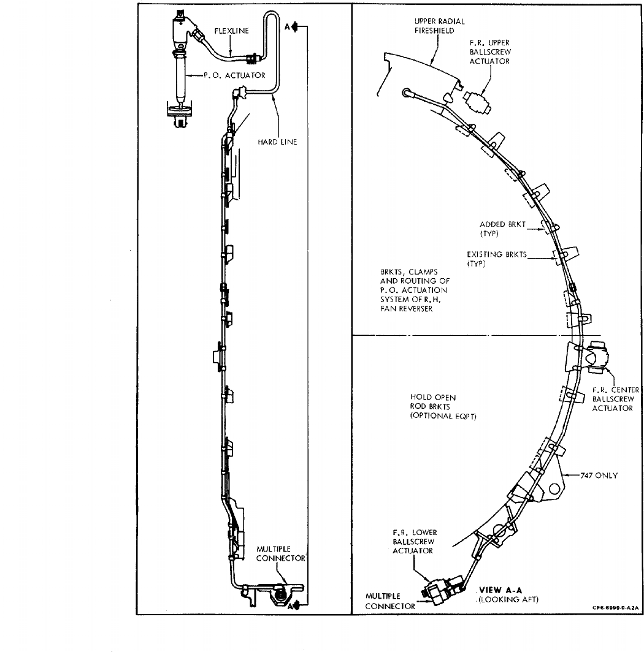 |
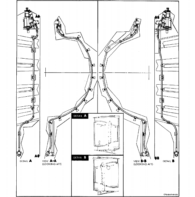
| Figure 1013 R/H Cowl Door Hard Line Routing |
| * * * FOR 45A2, 50C, 50C1, 50C2, 50C2-B, 50C2-F, 50C2-R, 50E, 50E1, 50E2 |
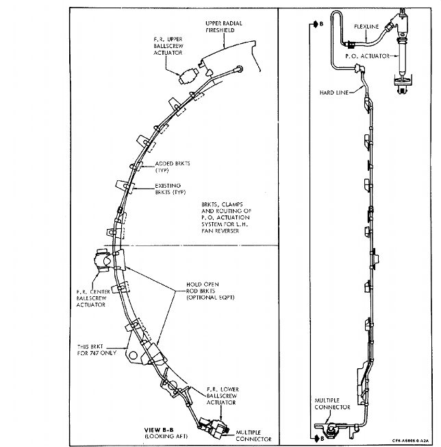 |
| Figure 1014 L/H Cowl Door Hard Line Routing |
| Subtask 78-32-00-440-064 |
| P. | Install cowl door hydraulic actuator and hard line tubes as follows: Refer to Figure 1011, Figure 1013 and Figure 1014. |
| (1) | Position the hydraulic actuator on cowl bracket with input fitting forward, install bolts and nuts then tighten to 55-70 lb-in. (6.2-7.9 N.m). |
| (2) | Extend the actuator, if necessary until clevis holes align with the pylon mount uniball. |
| (3) | Install bolt through clevis and uniball (2) washers under bolt head, (1) washer under nut). Tighten nut 80-100 lb-in. (9.0-11.3 N.m). |
| (4) | Connect the flex hose from actuator to the bulkhead fitting. Tighten both ends 135-150 lb-in. (15.2-16.9 N.m). |
| (5) | Route the hard lines around the cowl per Figure 1013 and Figure 1014, attach clamps and tighten nuts 24-27 lb-in. (2.7-3.1 N.m). |
| (6) | Tighten coupling nuts of tubes connected to bulk head fitting, multiple connector, and at mid connection of tubes to 135-150 lb-in. (15.2-16.9 N.m). |
| Subtask 78-32-00-470-051 |
| Q. | Assembly procedure for feedback bracket sub-assemblies. LEFT SIDE: (OFF AIRPLANE) Figure 1015 and Figure 1016. |
| (1) | Install cam spring and rod guides to slot in bracket. |
| (2) | Place cam over guide extensions. |
| (3) | Slide rod into cam and through guides. |
| (4) | Install bushings inside each end of spring. Position spring assembly onto rod as rod is being inserted through cam and guides. |
| (5) | Screw rod into cam until shoulder on rod bottoms on cam. Tighten rod 155-175 lb-in. (17.5-19.8 N.m). |
| (6) | Assure that clearance exists between cam and cam guide bracket on both sides. |
| NOTE: | Clearance must exist, but does not have to be equal each side. |
| (7) | Install followers onto brackets using shoulder bolts. Place a wave washer, flat washer, and wave washer under bolt head. Install flat washers between brackets and followers. Tighten bolts to 55-70 lb-in. (6.2-7.9 N.m) and safetywire. Refer to Figure 1019. |
| NOTE: | Assure that cam and guides are properly seated in track of bracket and lubricate all parts subject to relative motion with lubricant C02-003. |
| (8) | Depress guide in aft direction to allow stop assembly screw, washer and locknut to be installed through feedback bracket. Tighten nut 55-70 lb-in. (6.2-7.9 N.m). |
| NOTE: | Early assemblies had a bar stop assembly rather than the screw stop. For this type stop install bolts, washers and nuts. (Washers under nuts.) |
| (9) | Check cam assembly for free movement. A force of 50 lbs. (21.7 kg) maximum is employed to actuate assembly to full stow/deploy positions. Remove force and assembly must return to neutral position with no indications of binding or visible time delay. |
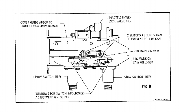
| NOTE: | Prior to installation of the limit switches, place the slotted cover over cam, aligning the antirotation sliders in the cover track. Install cover with (2) bolts and washers, then continue to install the switches. |
| (10) | Install indicator switches on lower side of bracket with bolts and washers. Tighten bolts 55-70 lb-in. (6.2-7.9 N.m) and safetywire. |
| (11) | Install setscrew with locknut to bracket. Adjust screws, with the followers in the non-cammed position, so follower contacts indicator switch plunger within 0.000-0.004 inch (0.00-0.1 mm). Check with feeler stock. Tighten locknut 55-70 lb-in. (6.2-7.9 N.m). |
| (12) | Check electrical indicator switches for continuity in Stow, deploy and neutral positions. Refer to Figure 1017 for pin configuration. |
| (a) | When the switch is in the free position, continuity should exist between pins B and C, and pins D and E. |
| (b) | When the switch is depressed, continuity should exist between pins A and B, and pins E and F. |
| (c) | When the switch is depressed to the actuation point (0.020-0.040 inch (0.51-1.02 mm)), continuity should change from pins B and C to pins A and B. |
| (13) | Install pneumatic limit switch with bolts and washers. Shim if necessary, with flat washer, to provide a minimum pretravel of 0.040 in. (1.0 mm) before poppet stems engage poppet valves. Tighten bolts 55-70 lb-in. (6.2-7.9 N.m) and safetywire. Refer to Figure 1018. |
| NOTE: | There are two types of follower pretension assemblies; 1) Set screw and locknut 2) Spring and bolt. With spring and bolt the followers are positioned correctly upon installation, with setscrew adjustments must be made as follows. |
| (14) | Flow check pneumatic limit switch to assure proper operation as follows: |
| (a) | Stow position - deploy line closed - stow line open to atmosphere. |
| (b) | Deploy position - deploy line open to atmosphere. |
| NOTE: | If all checks are acceptable and assembly completed, the sub-assembly is ready for installation. |
| * * * FOR 45A2, 50C, 50C1, 50C2, 50C2-B, 50C2-F, 50C2-R, 50E, 50E1, 50E2 |
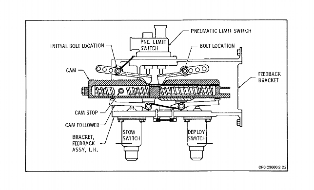 |
| Figure 1015 Left Side Feedback Assembly |
| * * * FOR 45A2, 50C, 50C1, 50C2, 50C2-B, 50C2-F, 50C2-R, 50E, 50E1, 50E2 |
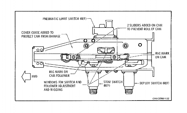 |
| Figure 1016 Left Side Feedback Assembly with Cover |
| * * * FOR 45A2, 50C, 50C1, 50C2, 50C2-B, 50C2-F, 50C2-R, 50E, 50E1, 50E2 |
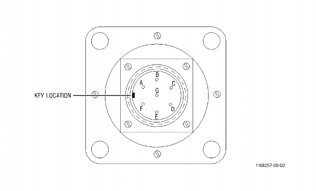 |
| Figure 1017 Indicator Switch Pin Configuration |
| * * * FOR 45A2, 50C, 50C1, 50C2, 50C2-B, 50C2-F, 50C2-R, 50E, 50E1, 50E2 |
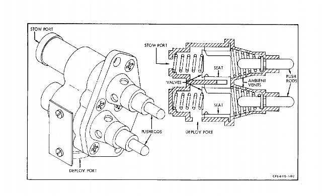 |
| Figure 1018 Pneumatic Limit Switch |
| * * * FOR 45A2, 50C, 50C1, 50C2, 50C2-B, 50C2-F, 50C2-R, 50E, 50E1, 50E2 |
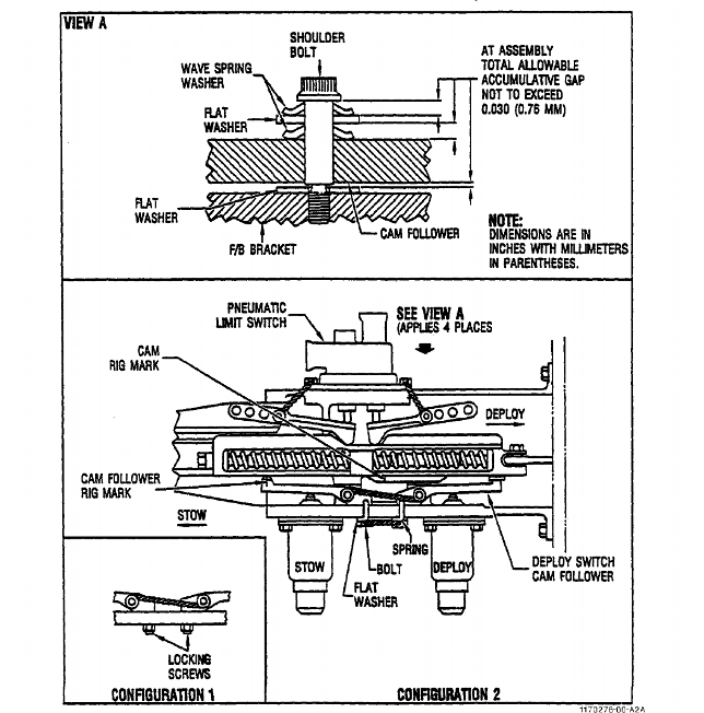 |
| Figure 1019 Feedback Cam Adjustment |
| Subtask 78-32-00-470-052 |
| R. | Assembly procedure for feedback bracket sub-assembly RIGHT SIDE: (OFF AIRPLANE) Figure 1020 and Figure 1021. |
| (1) | Install spring retainer to bracket and secure with bolt, washer and nuts. Position spring retainer toward indicator switch side of bracket and tighten nuts 55-70 lb-in. (6.2-7.9 N.m). |
| NOTE: | Feedback assemblies with slotted covers have shortened cams and do not have spring retainers. Insert the springs and rod through the cam, tighten and lockwire. |
| (2) | Place cam in bracket track, straddling retainer. |
| (3) | Insert rod into cam, placing small spring inside large spring then onto rod between retainer and cam. Push rod through retainer and install spring assembly onto rod. Thread rod into cam and tighten 155-175 lb-in. (17.5-19.8 N.m). |
| (4) | Assure that clearance exists between cam and cam guide bracket on both sides. |
| NOTE: | Clearance must exist but does not have to be equal on each side. |
| (5) | Install followers onto brackets with shoulder bolts. Place wave washers and flat washers under bolt heads. Install flat washers between brackets and followers. Tighten bolts to 55-70 lb-in. (6.2-7.9 N.m) and safetywire. |
| (6) | Install throttle interlock valve to bracket with bolts and washers. Tighten 55-70 lb-in. (6.2-7.9 N.m) and safetywire. |
| NOTE: | Lubricate cam, rod and all areas of relative motion with lubricant C02-003. |
| NOTE: | Prior to installation of limit switches, place the slotted cover over cam, aligning the anti-rotation sliders in the cover track. Install cover with (2) bolts and washers, then continue to install the switches. |
| (7) | Mount indicator switches to bracket with bolts and washers. Tighten 55-70 lb-in. (6.2-7.9 N.m) and safetywire. |
| (8) | Check assembly for freedom of movement. A force of 50 lbs. (21.7 kg) maximum is employed to actuate assembly to full stow/deploy positions. Remove force and assembly must return to neutral position with no indications of binding or visible time delay. |
| NOTE: | There are two types of follower pretension assemblies; 1) Set screw and locknut 2) Spring and bolt. With spring and bolt the followers are positioned correctly upon installation, with set screws adjustments must be made as follows: |
| (9) | Install setscrew and locknut to bracket. Adjust screws, with the followers in a non-cammed position, so followers contact indicator switch plunger within 0.000-0.004 in. (0.00-0.1 mm). Check with feeler stock. Tighten locknut 55-70 lb-in. (6.2-7.9 N.m). |
| (10) | Check electrical indicator switches for continuity in Stow, deploy and neutral positions. Refer to Figure 1017 for pin configuration. |
| (a) | When the switch is in the free position, continuity should exist between pins B and C, and pins D and E. |
| (b) | When the switch is depressed, continuity should exist between pins A and B, and pins E and F. |
| (c) | When the switch is depressed to the actuation point (0.020-0.040 inch (0.51-1.02 mm)), continuity should change from pins B and C to pins A and B. |
| * * * FOR 45A2, 50C, 50C1, 50C2, 50C2-B, 50C2-F, 50C2-R, 50E, 50E1, 50E2 |
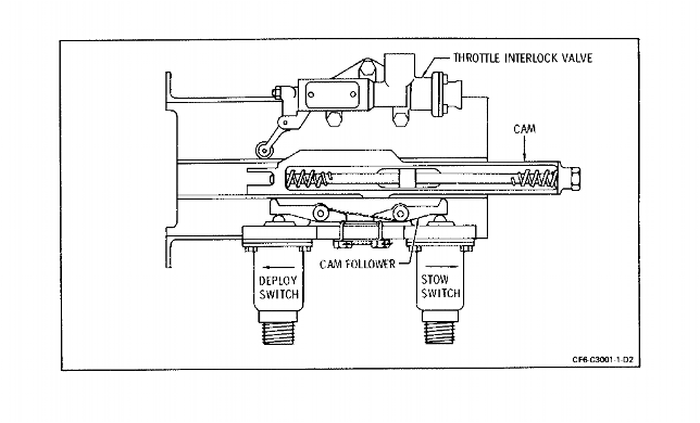 |
| Figure 1020 Right Side Feedback Assembly |
| * * * FOR 45A2, 50C, 50C1, 50C2, 50C2-B, 50C2-F, 50C2-R, 50E, 50E1, 50E2 |
 |
| Figure 1021 Right Side Feedback Assembly with Cover |
| Subtask 78-32-00-720-051 |
| S. | Flow check throttle interlock valve. |
| (1) | Apply 35-50 psig (271.3-344.7 kPa) pressure to inlet fitting. |
| (2) | Move cam to full deploy position and valve should vent through interlock actuator port. |
| NOTE: | If all checks are acceptable and assembly complete, place aside for later installation. |
| Subtask 78-32-00-440-065 |
| T. | Install feedback bracket assemblies: |
| (1) | Position bracket assembly over support bracket of fan reverser support assembly, aligning holes in brackets. Shim as required. |
| (2) | Install two bolts, washers and nuts through assemblies and tighten 55-70 lb-in. (6.2-7.9 N.m) of torque. |
| (3) | Install fire seal at support; tighten bolts to 24-27 lb-in. (2.7-3.1 N.m) of torque. |
| (4) | Insert feedback arm through support and fire seal. |
| (5) | Install feedback arm rod end bearing, tighten J-nut to 100-130 lb-in. (11.3-14.7 N.m) of torque. Connect arm to cam with bolt fingertight. |
| CAUTION: | DO NOT CONFUSE THE ORIFICE NIPPLES INSTALLED IN THE PNEUMATIC LIMIT SWITCH WITH THE STANDARD NIPPLES USED IN THE THROTTLE INTERLOCK VALVE. |
| (6) | Assemble new, lubricated O-rings to orifice nipples then install in pneumatic limit switch stow and deploy ports. Tighten to 180-200 lb-in. (20.3-22.6 N.m) of torque and safety-wire. |
| NOTE: | The orifice can be identified in the installed position by a 0.030 inch (0.8 mm) groove in two opposing wrenching flats. |
| (7) | Assemble new, lubricated O-rings on nipples and install in throttle interlock valve actuator and pressure ports. Tighten to 180-200 lb-in. (20.3-22.6 N.m) of torque and safety-wire. |
| (8) | Rig feedback assembly to translating cowl per paragraph 3. DD. (Subtask 78-32-00-83-052) referring to Figure 1019, Figure 1022, and Figure 1023. |
| Subtask 78-32-00-440-066 |
| U. | Install actuator assemblies on support: (Refer to Figure 1024). |
| CAUTION: | THIS PROCEDURE IS FOR THE ASSEMBLY OF THE BALLSCREW TO THE GEARBOX FOR THE PRE CF6-50 S/B 78-0224 TWO-PIECE ANGLE GEARBOX CONFIGURATION ONLY. FOR ASSEMBLY PROCEDURE OF BALLSCREW TO GEARBOX FOR POST CF6-50 S/B 78-0224 ONE-PIECE ANGLE GEARBOX CONFIGURATION, REFER TO COMPONENT MAINTENANCE MANUAL (CMM), 78-32-33, GEK 92496. |
| CAUTION: | ENSURE THAT ACTUATOR IS COMPLETELY BOTTOMED IN GEARBOX. |
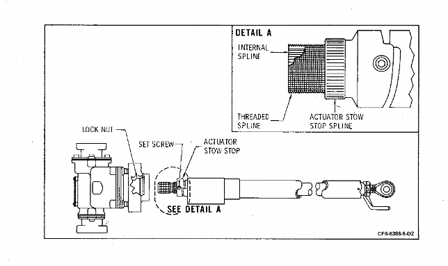
| (1) | Assemble ballscrew actuators in gearboxes. (Refer to Figure 1025 and Figure 1026.) |
| (a) | Mark radial and axial location of ballscrew actuator stop with respect to ballscrew. |
| NOTE: | Ballscrew stroke length is present to 22.14 ±0.010 inches (562.4 ±0.3 mm). |
| (b) | Remove actuator stop setscrew and carefully slide stop toward rod-end bearing to provide wrenching clearance. |
| (c) | Apply grease C02-014 to the ballscrew actuator internal spline, external threaded spline, and the actuator stop external spline. |
| (d) | Slide the ball screw onto the splined output shaft of the gearbox and thread the gearbox locknut onto the ballscrew actuator until the locknut bottoms. Use wrench MSE 43 and prevent the gearbox input shaft from rotating (or vice versa). |
| CAUTION: | ENSURE THAT ACTUATOR IS COMPLETELY BOTTOMED IN GEARBOX. |
| (e) | Tighten gearbox locknut to 150 lb in. (17.0 N.m) of torque using wrench MSE 43. |
| NOTE: | Nut has left-hand threads. |
| (f) | Backoff the locknut and retighten to 150 lb in. (17.0 N.m) of torque a minimum of three times to ensure ballscrew is fully seated. |
| (g) | Slide actuator stop into serrated inside diameter of gearbox locknut. Ensure that stop is on marked locations. |
| (h) | If stop serrations interfere with locknut serrations, slowly apply additional torque to maximum of 210 lb in. (23.7 N.m) while tapping firmly on exposed end of stop, using a plastic or other soft rod and hammer, until stop serra- tions enter locknut serrations. Adjust stop position axially to be on previously marked location. |
| CAUTION: | BALL RETURN TUBES MUST BE POSITIONED DOWN WITH ACUTATOR IN FLIGHT POSITION. |
| (2) | Position assemblies in actuator brackets and insert pins. Position retaining clips on pins, put a washer between the retaining clips and brackets and secure with bolts. Tighten bolts to 33-37 lb in. (3.7-4.2 N.m). |
| NOTE: | Secure assemblies to deflectors to prevent interference when translating cowl in installed. |
| * * * FOR 45A2, 50C, 50C1, 50C2, 50C2-B, 50C2-F, 50C2-R, 50E, 50E1, 50E2 |
 |
| Figure 1022 Right Side Feedback System Rigging |
| * * * FOR 45A2, 50C, 50C1, 50C2, 50C2-B, 50C2-F, 50C2-R, 50E, 50E1, 50E2 |
 |
| Figure 1023 Left Side Feedback System Rigging |
| * * * FOR 45A2, 50C, 50C1, 50C2, 50C2-B, 50C2-F, 50C2-R, 50E, 50E1, 50E2 |
 |
| Figure 1024 Typical Gearbox and Ball Screw Actuator Installation |
| * * * FOR 45A2, 50C, 50C1, 50C2, 50C2-B, 50C2-F, 50C2-R, 50E, 50E1, 50E2 |
 |
| Figure 1025 Assembly of Ball Screw Actuator in Gearbox |
| * * * FOR 45A2, 50C, 50C1, 50C2, 50C2-B, 50C2-F, 50C2-R, 50E, 50E1, 50E2 |
 |
| Figure 1026 Ball Screw Actuator Adjustment |
| Subtask 78-32-00-440-081 |
| * * * SB 78-3013 ( FAN REVERSERS WITH AN ELECTROMECHANICAL THRUST REVERSER ACTUATION SYSTEM (TRAS) LOCK FOR BOEING 747 ) |
| * * * SB 78-3025 ( FAN REVERSERS WITH AN ELECTROMECHANICAL THRUST REVERSER ACTUATION SYSTEM (TRAS) LOCK FOR BOEING DC-10 ) |
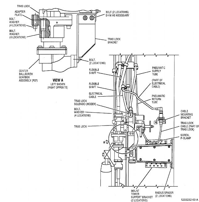
| V. | Install the thrust reverser actuation system (TRAS) lock as follows. Refer to Figure 1027. |
| (1) | If necessary, remove the trunnion pins and the retaining clips that attach the center gearbox to the actuator support so that you can move the actuator gearbox away from the actuator support. |
| (2) | Remove the adapter plate and the bracket from the TRAS lock as follows: |
| (a) | Remove the four bolts and the four washers that attach the adapter plate to the TRAS lock. |
| (b) | Remove the bracket from the TRAS lock as follows: |
| 1 | Remove the two bolts that attach the bracket to the TRAS lock. |
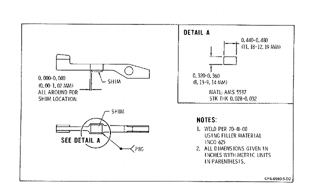
| 2 | Remove the shims between the bracket and the TRAS lock. |
| 3 | Keep the bolts and the shims for later use. |
| (3) | Install the adapter plate on the center ballscrew gearbox assembly with four screws and four washers. Tighten the screws to 50-55 lb in. (5.6-6.2 N.m). |
| (4) | Attach the bracket to the center ballscrew gearbox assembly with two screws. Do not tighten the screws. |
| (5) | Install the brake assembly as follows: |
| (a) | Put the square drive of the TRAS lock into the adapter plate attached to the center ballscrew gearbox assembly. |
| (b) | Attach the TRAS lock to the adapter plate with four bolts and four washers. |
| 1 | Tighten the bolts to 50-55 lb in. (5.6-6.2 N.m). |
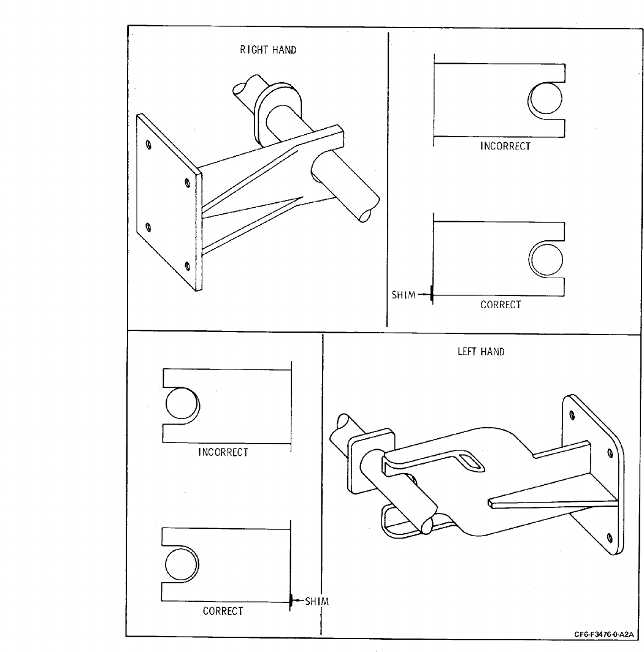
| (c) | Attach the TRAS lock to the TRAS lock bracket with two bolts. Use shims as necessary between the TRAS lock and the bracket for a tight fit. |
| 1 | Tighten the bolts to 110-120 lb in. (12.4-13.6 N.m). |
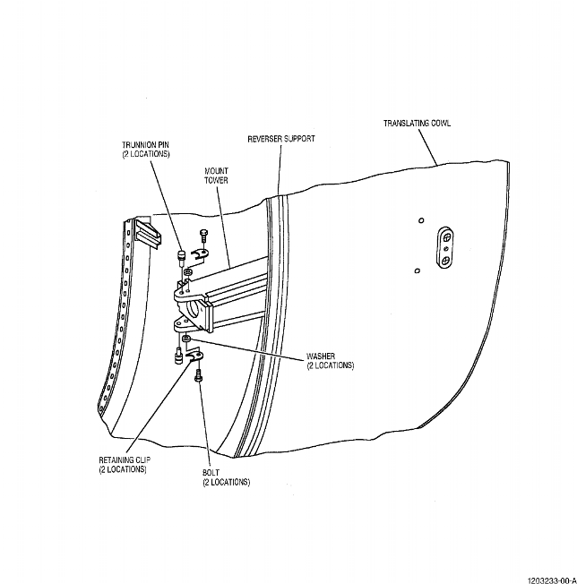
| (6) | Align the gearbox trunnion mounting holes with the mount tower clevis and insert the trunnion pins. Refer to Figure 1028. |
| (7) | Install the retaining clips as follows: |
| (a) | Attach the clips with the washers and bolts. |
| (b) | Install the washers between the clips and the mount tower. |
| (c) | Tighten the bolts to 24-27 lb in. (2.7-3.1 N.m). |
| (8) | Connect the TRAS lock cable as follows: |
| (a) | Connect the TRAS lock cable to the electrical cable mounting bracket. |
| (b) | Use the screw and the P-clamp to attach the TRAS lock cable to the mount tower support bracket at the nutplate. |
| 1 | Tighten the P-clamp hardware to 33-37 lb in. (3.7-4.2 N.m). |
| (9) | Install the electrical cable as follows: |
| (a) | Attach the electrical cable to the TRAS lock solenoid electrical connector and the electrical cable mounting bracket. |
| (b) | Attach the opposite end of the electrical cable to the electrical connector mounting bracket at the upper bulkhead with four screws, eight washers, and four self-locking nuts. |
| (c) | Use three P-clamps to attach the electrical cable to the three tube support brackets. Attach the P-clamps with a bolt, washer, and self-locking nut to make a triple P-clamp combination with the two tube clamps at each support bracket. Tighten the hardware to 33-37 lb in. (3.7-4.2 N.m). |
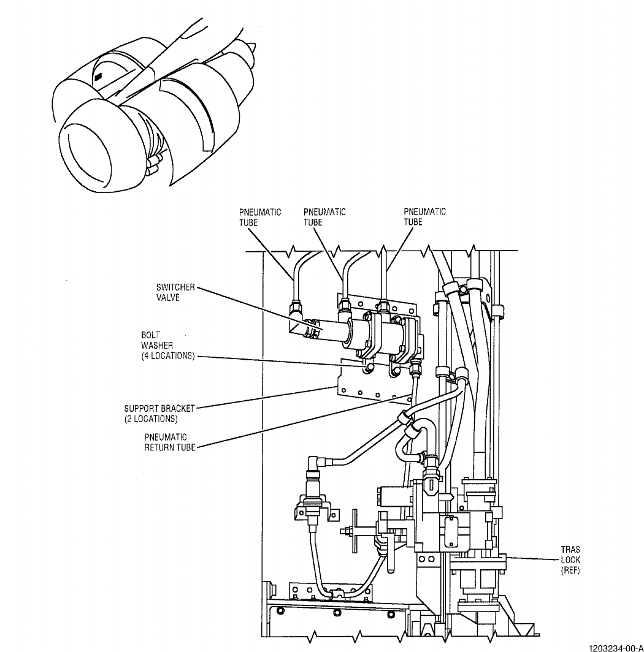
| (10) | Attach the switcher valve to the switcher valve support brackets on the right thrust reverser half with four self-locking bolts and four washers. Tighten the bolts to 33-37 lb in. (3.7-4.2 N.m). Refer to Figure 1029. |
| NOTE: | Pre service bulletins 78-3013 and 78-3025 do not use the above steps. Service bulletins 78-3013 and 78-3025 add a thrust reverser actuation system (TRAS) lock to the assembly procedure. |
| * * * END SB 78-3013 |
| * * * END SB 78-3025 |
| * * * FOR 45A2, 50C, 50C1, 50C2, 50C2-B, 50C2-F, 50C2-R, 50E, 50E1, 50E2 |
 |
| Figure 1028 Center Gearbox/Actuator Mount Tower |
| * * * FOR 45A2, 50C, 50C1, 50C2, 50C2-B, 50C2-F, 50C2-R, 50E, 50E1, 50E2 |
 |
| Figure 1029 Switcher Valve Installation |
| Subtask 78-32-00-440-067 |
| W. | Route air tubes from the throttle interlock valve and the pneumatic limit switch around the support. Tighten the coupling nuts to the valve, switch, and nipples on the structure to 270-300 lb in. (30.5-33.9 N.m). Safety the nuts with lockwire. Tighten the clamp bolts to 24-27 lb in. (2.7-3.1 N.m). |
| Subtask 78-32-00-440-082 |
| * * * SB 78-3013 ( FAN REVERSERS WITH AN ELECTROMECHANICAL THRUST REVERSER ACTUATION SYSTEM (TRAS) LOCK FOR BOEING 747 ) |
| * * * SB 78-3025 ( FAN REVERSERS WITH AN ELECTROMECHANICAL THRUST REVERSER ACTUATION SYSTEM (TRAS) LOCK FOR BOEING DC-10 ) |
| X. | Install the pneumatic tubes for the TRAS lock on the left thrust reverser half as follows: |
| NOTE: | There must be a minimum clearance of 0.125 inch (3.18 mm) between each pneumatic tube and the adjacent parts. |
| (1) | At the upper bulkhead, connect the 0.25 inch (6.4 mm) pneumatic return tube to the 0.25 inch (6.4 mm) tube union, and connect the 0.375 inch (9.53 mm) pneumatic supply tube to the 0.375 inch (9.53 mm) tube elbow. Do not tighten the coupling nuts. |
| (2) | Attach the return tube and the supply tube to the three support brackets. Use three P-clamps for the return tube, three P-clamps for the supply tube, and one washer, one self-locking nut, and one bolt at each P-clamp pair. Do not tighten the hardware. |
| (3) | Connect the return tube to the pneumatic return port (labeled RETURN) on the TRAS lock. |
| (4) | Connect the supply tube to the pneumatic supply port (labeled SUPPLY) on the TRAS lock. |
| (5) | Tighten the return tube coupling nuts to 135-155 lb in. (15.3-17.5 N.m). Tighten the supply tube coupling nuts to 270-300 lb in. (30.5-33.9 N.m). Tighten the P-clamp hardware for the supply tube and the return tube to 33-37 lb in. (3.7-4.2 N.m). |
| Subtask 78-32-00-440-083 |
| Y. | Install the pneumatic tubes for the TRAS lock and the switcher valve on the right thrust reverser half as follows: |
| NOTE: | There must be a minimum clearance of 0.125 inch (3.18 mm) between each pneumatic tube and the adjacent parts. |
| (1) | Attach one end of the TRAS lock supply tube to the in-line tee fitting located on the supply tube connected to the throttle interlock valve. Connect the opposite end of the TRAS lock supply tube to the TRAS lock pneumatic supply port labeled SUPPLY. Tighten the coupling nuts to 270-300 lb in. (30.5-33.9 N.m). |
| (2) | Connect the pneumatic return tube between the switcher valve and the TRAS lock pneumatic return port labeled RETURN. Tighten the coupling nuts to 135-155 lb in. (15.3-17.5 N.m). |
| (3) | Install three pneumatic tubes between the switcher valve and the upper bulkhead on the right reverser half. Tighten the coupling nuts of the pneumatic tubes to 135-155 lb in. (15.3-17.5 N.m). Attach the three pneumatic tubes to the flexible shaft assembly guide with P-clamps. Attach the three pneumatic tubes to the tube support bracket with P-clamps. Tighten the P-clamp hardware to 33-37 lb in. (3.7-4.2 N.m). |
| NOTE: | Pre service bulletins 78-3013 and 78-3025 do not use the above steps. Service bulletins 78-3013 and 78-3025 add a thrust reverser actuation system (TRAS) lock to the assembly procedure. |
| * * * END SB 78-3013 |
| * * * END SB 78-3025 |
| Subtask 78-32-00-440-068 |
| CAUTION: | ELECTRICAL CONNECTORS MUST BE TIGHTENED BY HAND ONLY. USE OF TOOL COULD RESULT IN DAMAGE TO CONNECTOR OR WIRING. |
| Z. | Route electrical cables from indicator switches around support. Tighten connectors at switches finger tight and safetywire; tighten clamp bolts to 24-27 lb-in. (2.7-3.1 N.m). |
| Subtask 78-32-00-440-069 |
| AA. | Install pod temperature sensing transducer and cable on left hand reverser half as follows: |
| (1) | Position transducer in mounting bracket and install lock nut; tighten to 492-570 lb-in. (55.6-64.4 N.m). |
| (2) | Install electrical connector; tighten fingertight and safetywire. |
| (3) | Slide lower end of cable aft through lower fire seal. |
| (4) | Connect cable at: |
| (a) | Pod transducer; tighten connector fingertight and safetywire. |
| (b) | Lower fire seal and interface bracket; tighten screws and nuts 10-12 lb-in. (1.1-1.4 N.m). |
| (c) | Distribute cable evenly around clamping brackets and install clamps; tighten clamp bolts to 24-27 lb-in. (2.7-3.1 N.m). |
| Subtask 78-32-00-440-070 |
| AB. | Position translating cowl in vertical position with leading edge down and install the following components: |
| (1) | Sound panels; tighten screws to 24-27 lb-in. (2.7-3.1 N.m). |
| NOTE: | After installation of all sound panels apply sealant C01-089 along the leading edge in a continuous bead. Smooth to the contour of the panels. This will minimize the potential of panel erosion/separation. |
| (2) | Blocker door clevises tighten bolts to 24-27 lb-in. (2.7-3.1 N.m). |
| NOTE: | Minimum of 1 1/2 threads must protrude through lock nuts; use longer bolts if required. |
| (3) | Blocker doors; tighten nuts to 55-70 lb-in. (6.2-7.9 N.m) and insert cotter pins. |
| NOTE: | Tighten nut to minimum torque of 55 lb. in. (6.2 N.m) and install cotter pin, if unable, continue torque application until the cotter pin will install. Do not apply more than 100 lb. in. (11.3 N.m) to nut. |
| NOTE: | Blocker door edges may require a minimal amount of trimming to assure proper seating. Any/all trimmed area/areas must be refinished per Repair No. 10. |
| NOTE: | Secure doors to cowl to prevent interference when cowl is installed. |
| (4) | Wear pads and bumper assemblies; tighten bolts to 13-16 lb-in. (1.4-1.8 N.m) and pad screws to 24-27 lb-in. (2.7-3.1 N.m). |
| NOTE: | Add shim/shims as necessary to obtain Dim. R as shown in Figure 1030. |
| (5) | Tee tracks on hinges; insert pins and secure with covers, then tighten screws. |
| * * * FOR 45A2, 50C, 50C1, 50C2, 50C2-B, 50C2-F, 50C2-R, 50E, 50E1, 50E2 |
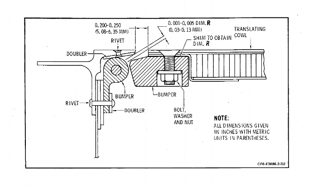 |
| Figure 1030 T/C to Bumper to Support Assembly Clearance |
| * * * FOR 45A2, 50C, 50C1, 50C2, 50C2-B, 50C2-F, 50C2-R, 50E, 50E1, 50E2 |
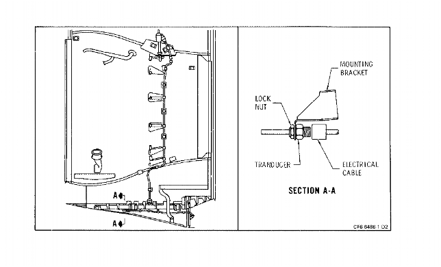 |
| Figure 1031 Pod Temperature Transducer Removal/Installation |
| Subtask 78-32-00-440-071 |
| AC. | Install translating cowl on support assembly: |
| CAUTION: | ENSURE THAT COWL DOES NOT CONTACT FEEDBACK RODS AS IT IS LOWERED ON SUPPORT. |
| (1) | Install sling and brackets, 2C6368, at sound panels on translating cowl and jack set, 2C6512, on cowl forward flange. |
| (2) | Lift cowl and engage cowl tee hinges in support assembly guides. Carefully lower cowl until supports are engaged on support flange. |
| (3) | Connect link assemblies to blocker doors. Tighten bolts and nuts finger tight and insert cotter pins. |
| (4) | Install feedback guide brackets and engage feedback rod; tighten screws to 24-27 lb-in. (2.7-3.1 N.m). |
| NOTE: | On left side reverser, no contact is allowed between rod and feedback yoke during any portion of cowl translation. If contact exists, install shims as required under yoke screws to prevent contact. |
| Subtask 78-32-00-440-072 |
| AD. | Adjust actuator rod end bearings and secure to cowl as follows: (Refer to Figure 1023). |
| CAUTION: | WITH REVERSER IN FLIGHT POSITION, ACTUATOR BALL RETURN TUBES MUST POINT DOWN. |
| (1) | Adjust jack set, 2C6512, to position translating cowl leading edge so that ball screw actuator rod end bearings are exposed. |
| (2) | Measure distance on translating cowl between clevis bolt hole center line and bumper assembly leading edge. This establishes dimension "A". |
| (3) | Set ball screw actuators on stow stops and loosen rod end bearing jam nuts. |
| (4) | Rotate each actuator rod in deploy direction (clockwise facing gearbox) to align anti-rotation lug with cowl clevis. |
| (5) | Using square drive on gearbox square socket, hold actuator on stow stop with anti-rotation lug in position. Do not exceed torque of 100 lb-in. (11.3 N.m). |
| (6) | Set distance between support assembly structural stop and actuator rod end mounting hole center line at dimension "A" plus 0.28-0.29 inch (7.11-7.37 mm) within one half revolution of rod end bearing. |
| (7) | Tighten rod end bearing jam nut while you keep the rod end from turning. |
| (a) | For ballscrew assemblies P/N 121210 series or P/N 3275506 series, torque the rod end bearing jam nut to 180-220 lb in. (20.3-24.9 N.m) and safetywire. |
| (b) | For ballscrew assemblies P/N 3238911 series, torque the rod end bearing jam nut to 500-520 lb in. (56.5-58.8 N.m) and safetywire. |
| NOTE: | After final end adjustment, a 0.055 inch (13.9 mm) dia. pin must not pass through witness hole. |
| CAUTION: | IF TOOL IS NOT USED, ENSURE THAT PINS ARE INSTALLED WITH THREADED ENDS OUTBOARD. |
| (8) | Drive through gearbox and align with cowl clevis to extend each actuator. Insert pin and cover assembly. Use puller, 2C6367, with adapter. Tighten pin cover screws to 24-27 lb in. (2.7-3.1 N.m). |
| NOTE: | Hold actuator rod to prevent rotation until rod end is within translating cowl clevis. |
| Subtask 78-32-00-440-073 |
| AE. | Route the flexible shafts around the support and install clamps. Clamp bracket and fire seal at upper firewall. Tighten clamp bolts and fire seal nuts to 24-27 lb in. (2.7-3.1 N.m). Tighten bracket bolt to 55-70 lb in. (6.2-7.9 N.m). Install guide channel bolt and spacer. Tighten to 55-70 lb in. (6.2-7.9 N.m). |
| NOTE: | Clamp center line must be aligned with shaft center line. Bend radii must be no less than 10.0 inches (254 mm). |
| Subtask 78-32-00-440-074 |
| * * * PRE SB 78-3013 ( FAN REVERSERS WITHOUT AN ELECTROMECHANICAL THRUST REVERSER ACTUATION SYSTEM (TRAS) LOCK FOR BOEING 747 ) |
| * * * PRE SB 78-3025 ( FAN REVERSERS WITHOUT AN ELECTROMECHANICAL THRUST REVERSER ACTUATION SYSTEM (TRAS) LOCK FOR BOEING DC-10 ) |
| AF. | Install flexible shafts at gearboxes as follows: |
| (1) | Engage the interconnecting shafts in the end gearboxes. Tighten the flange bolts to 24-27 lb in. (2.7-3.1 N.m) of torque. |
| (2) | Temporarily install the interconnecting shafts into the center gearbox. This lets the end gearboxes help drive the cowl to stow position before the reverser is adjusted. |
| (3) | Drive through the center gearbox unused pad to remove the jack set and translate the cowl to stow position. |
| (4) | Disconnect the interconnecting shafts from the center gearbox. |
| (5) | Hold the end and center gearboxes firmly on the stow stops. |
| (6) | Insert the interconnecting shafts into the center gearbox again. If the square drive end of the shaft is not aligned to the gearbox drive port, release pressure on the gearbox only enough to let the shaft drive enter. |
| NOTE: | The maximum release of pressure for the center gearbox is one flat of the drive square into which the shaft is being inserted. |
| (7) | Tighten the flange bolts to 24-27 lb in. (2.7-3.1 N.m) of torque. |
| (8) | Do this procedure again for other interconnecting shafts. |
| (9) | Partially translate the cowl and restow with the center gearbox input socket. Running torque must not be more than 25 lb in. (2.8 N.m) to translate cowl within gap limits. |
| (10) | If you go above torque limits, check for actuator lubrication, interference between the cowl and support assembly, or bumper rigging of dimension R 0.001-0.005 inch (0.03-0.13 mm). Correct as necessary. |
| * * * END PRE SB 78-3013 |
| * * * END PRE SB 78-3025 |
| Subtask 78-32-00-440-084 |
| * * * SB 78-3013 ( FAN REVERSERS WITH AN ELECTROMECHANICAL THRUST REVERSER ACTUATION SYSTEM (TRAS) LOCK FOR BOEING 747 ) |
| * * * SB 78-3025 ( FAN REVERSERS WITH AN ELECTROMECHANICAL THRUST REVERSER ACTUATION SYSTEM (TRAS) LOCK FOR BOEING DC-10 ) |
| AF. A. | Install flexible shafts at gearboxes as follows: |
| (1) | Engage the interconnecting shafts in the end gearboxes. Tighten the flange bolts to 24-27 lb. in. (2.7-3.1 N.m) of torque. |
| (2) | Temporarily connect the interconnecting shafts to the TRAS lock and the center gearbox. This lets the center gearbox help drive the cowl to stow position before the reverser is adjusted. |
| (3) | Drive through the center gearbox unused pad to remove the jack set and translate the cowl to stow position. |
| (4) | Disconnect the interconnecting shafts from the TRAS lock and the center gearbox. |
| (5) | Hold the end and center gearboxes firmly on the stow stops. |
| (6) | Insert the interconnecting shafts into the TRAS lock and the center gearbox again. If the square drive end of the shaft is not aligned to the gearbox drive port, release pressure on the gearbox only enough to let the shaft drive enter. |
| NOTE: | The maximum release of pressure for the center gearbox is one flat of the drive square into which the shaft is being inserted. |
| (7) | Tighten the flange bolts to 24-27 lb. in. (2.7-3.1 N.m) of torque. |
| (8) | Do this procedure again for other interconnecting shafts. |
| (a) | Manually release the TRAS lock for manual translation of the cowl. Make sure the TRAS lock is released when you measure the running torque. |
| (9) | Partially translate the cowl and restow with the center gearbox input socket. Running torque must not be more than 25 lb. in. (2.8 N.m) to translate cowl within gap limits. |
| (10) | If you go above torque limits, check for actuator lubrication, interference between the cowl and support assembly, or bumper rigging of dimension R 0.001-0.005 inch (0.03-0.13 mm). Correct as necessary. |
| * * * END SB 78-3013 |
| * * * END SB 78-3025 |
| Subtask 78-32-00-830-051 |
| * * * PRE SB 78-3013 ( FAN REVERSERS WITHOUT AN ELECTROMECHANICAL THRUST REVERSER ACTUATION SYSTEM (TRAS) LOCK FOR BOEING 747 ) |
| * * * PRE SB 78-3025 ( FAN REVERSERS WITHOUT AN ELECTROMECHANICAL THRUST REVERSER ACTUATION SYSTEM (TRAS) LOCK FOR BOEING DC-10 ) |
| AG. | Do a check of the rigging as follows: |
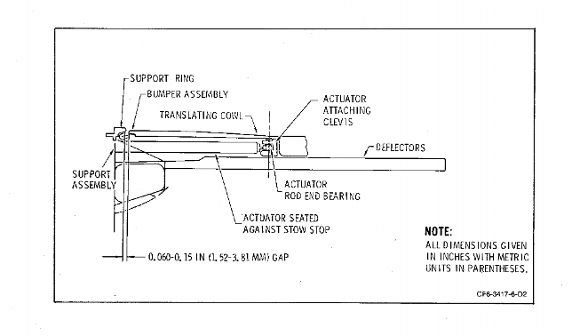
| (1) | Deploy the reverser slightly and restow. Measure the input torque to the center gearbox just before actuator reaches stow stop. If there is more than 25 lb in. (2.8 N.m) of torque, adjust rod end bearing or make sure structural interference is correct. |
| (2) | With actuators held on stow stops, do a check of the gap between the translating cowl and the support assembly. There must be a 0.06-0.15 inch (1.5-3.8 mm) gap. If the gap is out of limits, adjust the actuator rod end bearings as necessary. |
| NOTE: | If rod end adjustment is made, do a check of the center gearbox input torque again. |
| (3) | With reverser stowed, check gap between outside of bumper lock plate and support assembly; 0.02 inch (0.5 mm) gap must exist. If necessary, install shims between plate and translating cowl to achieve required gap. Refer to Figure 1032. |
| * * * END PRE SB 78-3013 |
| * * * END PRE SB 78-3025 |
| * * * FOR 45A2, 50C, 50C1, 50C2, 50C2-B, 50C2-F, 50C2-R, 50E, 50E1, 50E2 |
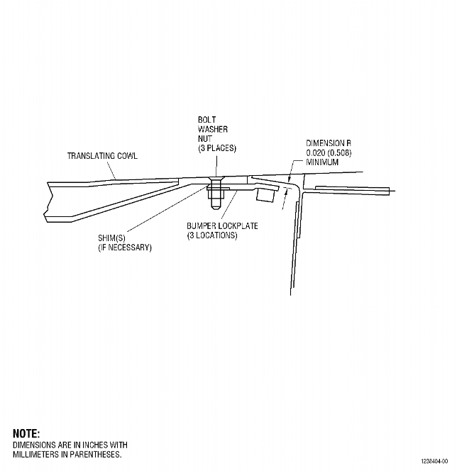 |
| Figure 1032 Translating Cowl Bumper Lock Plate Replacement |
| Subtask 78-32-00-830-053 |
| * * * SB 78-3013 ( FAN REVERSERS WITH AN ELECTROMECHANICAL THRUST REVERSER ACTUATION SYSTEM (TRAS) LOCK FOR BOEING 747 ) |
| * * * SB 78-3025 ( FAN REVERSERS WITH AN ELECTROMECHANICAL THRUST REVERSER ACTUATION SYSTEM (TRAS) LOCK FOR BOEING DC-10 ) |
| AG. A. | Do a check of the rigging as follows: |
| (1) | Manually release the TRAS lock. |
| (2) | Deploy the reverser slightly and restow. Measure the input torque to the center gearbox just before actuator reaches stow stop. If there is more than 25 lb in. (2.8 N.m) of torque, adjust rod end bearing or make sure structural interference is correct. |
| (3) | Do a check of the gap between the translating cowl and the support assembly with actuators held on stow stops. There must be a 0.06-0.15 inch (1.5-3.8 mm) gap. If the gap is out of limits, adjust the actuator rod end bearings as necessary. |
| NOTE: | If rod end adjustment is made, do a check of the center gearbox input torque again. |
| (4) | Do a check of the gap between the outside of the lock plate and the support assembly with reverser stowed. There must be a gap of 0.02 inch (0.5 mm). If necessary, install shims between the plate and the translating cowl to get the necessary gap. |
| Subtask 78-32-00-220-052 |
| (5) | Do a torque check of the TRAS lock as follows: |
| (a) | Remove the two bolts that attach the pad cover and the gasket (or the splined lock) to the manual drive pad on the center ballscrew gearbox assembly, on the right thrust reverser half. |
| (b) | Remove the pad cover and gasket or the splined lock. |
| (c) | Manually release the TRAS lock. |
| (d) | Manually deploy the translating cowl on the right thrust reverser half a minimum of 1.0 inch (25 mm). |
| NOTE: | This procedure uses a splined adapter tool that you insert into the manual drive pad on the center ballscrew gearbox assembly. You can attach a torque wrench to the splined adapter. If necessary, you can make the splined adapter tool from the end of a discarded flex shaft cable. Refer to Figure 1033. |
| 1 | Make sure you deploy the translating cowl a minimum of 1.0 inch (25 mm) to prevent an incorrect torque reading. This will remove all torque that could occur if the translating cowl bumpers touch the fixed structure. |
| (e) | Manually engage the TRAS lock on the right thrust reverser half as follows: |
| 1 | Pull the T-handle approximately 0.1 inch (3 mm). |
| 2 | Turn the manual release lever away from the fan cowl. |
| 3 | Engage the manual release lever in the retaining clip. |
| 4 | Release the T-handle. |
| (f) | Make sure the manual drive lockout cover is removed and install the locally made splined adapter tool and a dial-type torque wrench into the manual drive pad of the center ballscrew gearbox assembly. |
| (g) | Turn the torque wrench in the deploy direction until the torque is 180 lb in. (20.3 N.m). |
| 1 | Make a mark at the point where you start to apply the torque. This will help you know how far you turned the wrench in the step that follows. |
| 2 | The TRAS lock system operates correctly if you get 180 lb in. (20.3 N.m) of torque before you turn the wrench one-half turn. If you do not get to 180 lb in. (20.3 N.m) of torque, make sure you turned the wrench in the deploy direction. If you turn the wrench in the deploy direction and cannot reach 180 lb in. (20.3 N.m) of torque, you must replace the TRAS lock. |
| 3 | Record the results of the holding torque check. |
| 4 | Turn the wrench slowly in the stow direction to release the torque. Turn the wrench until you get 0 lb in. (0 N.m) of torque. |
| 5 | Install the pad cover and the gasket (or the splined lock) on the lower side of the center ballscrew gearbox assembly with the two bolts. |
| (h) | Do Subtask 78-32-00-220-052 again for the left reverser half. |
| * * * END SB 78-3013 |
| * * * END SB 78-3025 |
| * * * FOR 45A2, 50C, 50C1, 50C2, 50C2-B, 50C2-F, 50C2-R, 50E, 50E1, 50E2 |
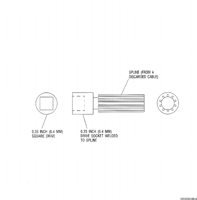 |
| Figure 1033 Splined Adapter Tool |
| Subtask 78-32-00-440-075 |
| AH. | Install actuator bracket covers and gaskets; tighten to 24-27 lb-in. (2.7-3.1 N.m). |
| Subtask 78-32-00-830-052 |
| AI. | Adjust the feedback assemblies as follows. Refer to Figure 1024, Figure 1025, and Figure 1019. |
| Subtask 78-32-00-830-054 |
| * * * SB 78-3013 ( FAN REVERSERS WITH AN ELECTROMECHANICAL THRUST REVERSER ACTUATION SYSTEM (TRAS) LOCK FOR BOEING 747 ) |
| * * * SB 78-3025 ( FAN REVERSERS WITH AN ELECTROMECHANICAL THRUST REVERSER ACTUATION SYSTEM (TRAS) LOCK FOR BOEING DC-10 ) |
| (1) | Manually release the TRAS lock. |
| NOTE: | Pre service bulletins 78-3013 and 78-3025 do not use this step. Service bulletins 78-3013 and 78-3025 add a thrust reverser actuation system (TRAS) lock to the procedure to adjust the feedback assemblies. |
| * * * END SB 78-3013 |
| * * * END SB 78-3025 |
| Subtask 78-32-00-830-055 |
| (2) | Position translating cowl at neutral position (deploy the cowl 4.0-4.5 inches (102-114 mm) aft of fully stowed position). |
| (3) | Disconnect feedback rod end bearing fitting. |
| (4) | Push cam forward or away from translating cowl until it bottoms, then retract 0.10-0.16 inch (2.5-4.1 mm) and hold in this position. |
| (5) | Stow the translating cowl and hold on the stops. Push the feedback rod aft until it contacts the yoke. This positions the forward feedback rod stow stop against the forward face of the feedback yoke. |
| (a) | While holding the rod in this position, adjust the rod end bearing fitting until the holes align, and connect the rod to the feedback cam. |
| (6) | Release cam and deploy translating cowl. |
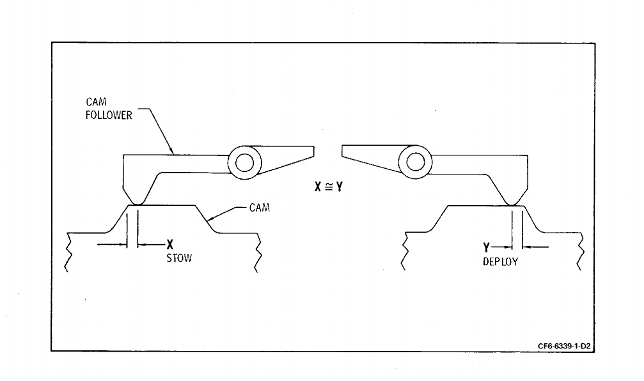
| (a) | Check for cam overtravel movement of 0.100-0.160 inch (2.5-4.1 mm). |
| (b) | Stow cowl and recheck to assure that 0.100-0.160 inch (2.5-4.0 mm) overtravel exists in stowed position. |
| NOTE: | If insufficient end play exists - adjust cam to equally divide overtravel between ends. |
| (c) | On left side reverser, stow cam follower must rest on top of cam lobe, 0.250 inch (6.4 mm) from edge, within one revolution of rod end bearing, or if cover is installed, the aligning marks on cam and cam follower should be aligned. |
| NOTE: | With feedback system properly rigged, indicator switches will be tripped at approximately equal points in cam stroke. |
| NOTE: | Cam follower configuration may differ among feedback assemblies. |
| (7) | Secure feedback arm to cam; tighten bolt to 55-70 lb-in. (6.21-7.91 N.m) and safetywire. Tighten rod end fitting jam nuts 40-50 lb-in. (4.52-5.65 N.m). |
| (8) | On right-hand feedback only, adjust the cam follower set screws, with follower in non-cammed position, so that the follower contacts the switch plunger within minus 0.000 to plus 0.004 inch (0.00-0.10 mm). |
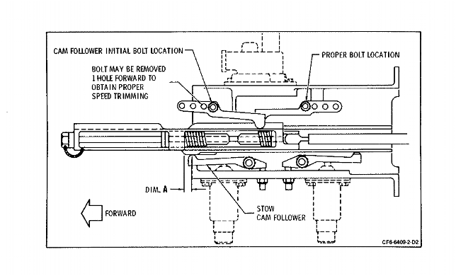
| (9) | On left-hand feedback system, ensure that the cam follower bolts are installed as shown in Figure 1019. |
| Subtask 78-32-00-820-051 |
| AJ. | Shim feedback electrical switches as follows: |
| NOTE: | There are two switch configurations in use and therefore two methods of checking and adjusting their pretravel. |
| (1) | The following instructions apply to switches P/N 9037M63P01 and P/N 9037M63P02. |
| (a) | Remove the switches. |
| (b) | Add five 0.013-0.019 inch (0.33-0.48 mm) thick shims to each switch mounting surface so the shims will be between the electrical switch and the feedback mating surfaces. |
| NOTE: | Standard AN thin aluminum washers for 10-32 bolts may be used as shims. |
| (c) | Reinstall the switches. |
| (d) | With the switches in the cammed position, measure the gap between the cam follower and the cam lobe. The gap must be as follows: |
| Left-hand switches 0.001-0.032 inch (0.03- 0.8 mm). Right-hand switches 0.001-0.016 inch (0.03- 0.4 mm). |
| (e) | If the gap is less than 0.001 inch (0.03 mm) additional shims are required until the correct gap is attained. |
| (f) | If the gap is greater than 0.016 inch (0.4 mm) for right-hand switches or greater than 0.032 inch (0.81 mm) for left-hand switches, the cam followers are probably discrepant, due to wear, and should be reinspected and/or replaced. |
| (g) | If the gap meets requirements, no additional shimming is necessary. |
| (h) | When the required gap is attained, remove five shims; the remaining shims must be installed with the switches to provide proper plunger travel. |
| (i) | Reinstall the switch; tighten mounting bolts to 33-37 lb in. (3.7-4.2 N.m) of torque. |
| (2) | The following instructions apply to switches P/N 9037M63P01 RW, 9037M63P03, 9037M63P04, 9037M63P05, and 9037M63P06. |
| (a) | Install reworked/new switches to the mounting surfaces of the bracket. Tighten the nuts to seat each switch in the cammed position. |
| (b) | With the switches in the cammed position, measure the gap between the cam and the cam follower. The gap shall be as follows: |
| Left-hand switches 0.002-0.032 inch (0.05- 0.81 mm) Right-hand switches 0.002-0.016 inch (0.05- 0.41 mm) |
| (c) | If the gap is less than 0.002 inch (0.05 mm), add shims as required between switch and switch base. |
| (d) | If the gap is more than 0.016 inch (0.41 mm) for the right-hand switches or more than 0.032 inch (0.81 mm) for the left-hand switches, check the follower for wear. |
| (e) | Repair or replace the switches as necessary. |
| (f) | Tighten the mounting bolts to 33-37 lb in. (3.7- 4.2 N.m) of torque. |
| 4. | Inspect/Check. |
| The following inspection checks must be made periodically to be sure of proper reverser system operation. |
| Subtask 78-32-00-220-051 |
| NOTE: | If condition or adjustment of a component is questionable, refer to serviceable limits for individual component. |
| A. | Feedback system. (Refer to Figure 1019, Figure 1022, and Figure 1023). |
| (1) | System must be properly rigged per paragraph 3.DD. (Subtask 78-32-00-830-052) |
| (2) | Cam followers must rotate freely by hand. Accumulative gap in the shoulder bolt/washer/cam follower assembly must not exceed 0.030 inch (0.8 mm). |
| (3) | If gap exceeds 0.030 inch (0.8 mm), add (2) wave washers and replace washer with locally manufactured spacer as shown in Figure 1019. |
| NOTE: | After installation of wave washers and spacer, recheck assembly to assure that followers rotate freely. If assembly is excessively preloaded, prohibiting movement, remove (1) wave washer. |
| (4) | With the followers in the non-cammed position, check gap of L/H stow and deploy indicator switches and followers by backing locking screws from contact with the followers. With the followers in full contact with the cam, measure the gap between the follower and the indicator switch plunger. If gap is less than 0.050 inch (1.3 mm), it is acceptable; if 0.050-0.080 inch (1.3-2.0 mm), add a 0.030 inch shim; if 0.081 (2.1 mm) or greater, add a 0.060 inch (1.5 mm) shim. (Shims to be added as shown in Figure 1034). |
| CAUTION: | DO NOT ADD EXCESSIVE SHIM STOCK, AS THIS MAY RESULT IN ACTIVATING THE SWITCHES IN A STATIC CONDITION. |
| (5) | Measure the gap between the lobe of foller and feedback cam, insert shim stock to fill the gap and then add an additional 0.005 inch (0.13 mm) stock to slightly preload the follower. |
| (6) | Adjust the locking screw until contact is made with follower. Then lock in place with locknut, and remove shim stock. The switches will be preloaded approximately 0.002 inch (0.05 mm). |
| NOTE: | If the feedback system has springs instead of set-screws, install the spring with bolts, tighten and safetywire. |
| (7) | Bushings must be properly positioned in guide. |
| (8) | Feedback cam must be capable of overtravel in both stow and deploy positions. |
| (9) | Feedback system parts having relative motion must be lubricated with lubricant C02-003. |
| (10) | Feedback rod must not contact feedback yoke during stow or deploy cycle. Refer to Figure 1035. |
| (11) | Shim the feedback yoke as necessary to attain the required clearance. |
| Subtask 78-32-00-440-076 |
| B. | Deploy reverser and check for contact between blocker door slot end and link arm. Trim slot end as required to eliminate interference. |
| Subtask 78-32-00-440-077 |
| C. | Stow reverser. |